Multicast Routing Protocols#
Note: Multicast routing protocols can be configured and run only if licenses for component 3 (advanced routing) is available
Multicasting is one source sending a packet to multiple destinations. Group formation and management is an integral part of multicasting.
IP Multicast Group Addressing: A multicast group is identified by its multicast group address. Multicast packets are delivered to that multicast group address. Unlike unicast addresses that uniquely identify a single host, multicast IP addresses do not identify a particular host. To receive the data sent to a multicast address, a host must join the group that address identifies. The data is sent to the multicast address and received by all the hosts that have joined the group indicating that they wish to receive traffic sent to that group. The multicast group address is assigned to a group at the source.
IP Class D Addresses: IP multicast addresses have been assigned to the IPv4 Class D address space by IANA. The high-order four bits of a Class D address are 1110. Therefore, host group addresses can be in the range 224.0.0.0 to 239.255.255.255. A multicast address is chosen at the source (sender) for the receivers in a multicast group.
NetSim supports the following protocols to implement IP multicast routing:
-
IGMP is used between hosts on a LAN and the routers on that LAN > to track the multicast groups of which hosts are members.
-
Protocol Independent Multicast (PIM) is used between routers so > that they can track which multicast packets to forward to each > other and to their directly connected LANs.
IGMP#
Introduction#
About Multicasting
Multicasting is a data delivery method where one sender sends data to thousands of recipients across a routed network. Multicasting is controlled broadcasting; the sender transmits data to specific recipients only.
With IP multicasting, a host sends packets to a multicast group of hosts anywhere within the IP network by using a special form of IP address called the IP multicast group address. A multicast group is made of an arbitrary number of hosts who join a group to receive packets from the source. To ensure that a host receives data, the host must join the multicast group to which the sender is sending data.
Note: You can configure and simulate multicast routing protocols such as IGMP and PIM, only if you have licenses for component 3 (advanced routing).
About IGMP
The Internet Group Management Protocol (IGMP) is a communication protocol that hosts and adjacent multicast routers on IPv4 networks use, to establish and manage the membership of hosts and routing devices in multicast groups. Hosts and multicast routers use IGMP as follows:
-
The hosts use IGMP to report their multicast group memberships to > neighboring multicast routers.
-
The multicast routers use IGMP to know the members in multicast > groups, for every physical network the multicast router is > connected.
The multicast routers maintain a list of multicast group memberships for every network to which the multicast routers are connected, and a timer for each membership.
The messages that IGMP uses are encapsulated in IP datagrams, with an IP protocol number of 2. All IGMP messages are sent with an IP TTL of 1 and contain the IP Router Alert option in their IP header. All IGMP messages sent between a host and the multicast router use the following format:

Figure 1‑1: IGMP datagrams
-
Type: There are three types of IGMP messages that hosts and > multicast routers exchange, when they interact:
-
0x11: Membership Query
There are two sub-types of Membership Query messages:
-
General Query: The multicast router sends a General Query to all > hosts to collect and update multicast group membership information > for the hosts on all networks to which the multicast router is > connected.
-
Group-Specific Query: The multicast router sends Group-Specific > Query to the multicast group from which it received a leave group > message, to find out if other hosts in the group require multicast > data.
-
0x16: Version 2 Membership Report
Version 2 Membership Report is a message that a host sends to all other hosts in the group or all hosts on the network, in response to a General Query or a Group-Specific Query message from the multicast router.
- 0x17: Leave Group (Not available with NetSim)
Hosts use the Leave Group message to tell the multicast router that they intend to leave the group.
-
Max Response Time: Maximum Response Time is a random-value delay > timer which a host sets, for the host to send a Version 2 > Membership Report to other hosts in the group, after the host > receives a Group-Specific Query message.
-
Checksum: The Checksum is the 16-bit one's complement of the > one's complement sum of the whole IGMP message (the entire IP > payload).
-
Group Address: The multicast router sets the Group Address to > zero when it sends a General Query and sets to the Group Address > to the address of the multicast group when it sends a > Group-Specific Query.
How IGMP Works
If a router has multiple physical interfaces on a single network, IGMP runs only on one of physical interfaces. Hosts, on the other hand, need to use all interfaces that have memberships associated with them.
For every network the multicast router is connected to, the multicast router performs one of the following roles: Querier or Non-Querier. There is normally only one Querier per physical network.
At startup, all multicast routers start as a Querier on every network to which the multicast routers are connected. If a multicast router hears a Query message from another multicast router with a lower IP address, the first multicast router must perform the role of a Non-Querier on the network which has the multicast router with a lower IP address. If a multicast router does not hear a Query message from another multicast router for a time duration defined by the Other Querier Present Interval, the multicast router persists with the role of the Querier.
Now, the multicast router sends one of the two Membership Query messages:
- General Query to all hosts to collect and update multicast group > membership information: The multicast router sends the General > Query to the all-systems multicast group (224.0.0.1), with a Group > Address field set to 0, and with a Max Response Time for the Query > Response Interval.
When a host receives the General Query, the host sets the delay timers for every group (excluding the all-systems group) to which the host belongs, on the interface on which it received the query.
The host sets every timer to a different random value, by using the highest clock granularity available on the host, and by choosing a value between 0 and the Max Response Time. The Max Response Time is specified in the General Query packet.
- Group-Specific Query to the multicast group from which it received > a leave group message: The multicast router sends the > Group-Specific Query to the multicast group from which it received > a leave group message, and with a Max Response Time for the Query > Response Interval. This helps the multicast router to learn if > there are other members on the group and if the group needs > multicast data.
When a host receives the Group-Specific Query, the host sets the delay timers for every group to which the host belongs, on the interface on which it received the query.
The host sets every timer to a different random value by choosing a value between 0 and the Max Response Time. The Max Response Time is specified in the Group-Specific Query packet.
If the delay timer for a group has started, the host resets the delay time to a random value only if the requested Max Response Time is less than the time left in the active delay timer.
When a group's delay timer expires, the host multicasts a Version 2 Membership Report to other hosts in the group, with an IP TTL of 1. If the host receives a Version 2 Membership Report (version 1 or 2) from another host in the same group, when the host’s timer is active, the host stops the timer for the group from which it received the report. The host also does send a report to other hosts, to avoid duplicate reports and conserve the bandwidth on the network.
When a multicast router receives a Version 2 Membership Report, it does the following:
-
Adds the multicast group from which it received the Version 2 > Membership Report, to the list of multicast group memberships on > the network on which it received the Version 2 Membership Report.
-
Sets the timer for the membership to the Group Membership Interval.
-
Refreshes the timer, when the multicast router receives another > Version 2 Membership Report from the same group.
If the multicast router does not receive any Version 2 Membership Reports from a multicast group before the Group Membership Interval timer expires, the multicast router assumes that the group has no members and that it need not forward multicast data for that group.
The multicast router may also receive an unsolicited Version 2 Membership Report from a host when the hosts intends to join a multicast group.
PIM#
Introduction#
Protocol-Independent Multicast or PIM is a group of multicast routing protocols for Internet Protocol (IP) networks. PIM distributes data in one-to-many and many-to-many multicast modes over a LAN, WAN or the Internet. PIM builds Multicast Distribution Tree (MDT) loop-free trees to enable multicast data distribution over a network.
PIM is termed protocol-independent because PIM does not include its own topology discovery mechanism; PIM uses routing information available from other routing protocols such as Enhanced Interior Gateway Routing Protocol (EIGRP), Open Shortest Path First (OSPF), and static routes.
PIM also does not build its own routing tables. PIM uses the unicast routing table that IGP creates, to create a loop free MDT and uses the unicast routing table to perform the reverse path forwarding (RPF). Unlike other routing protocols, PIM does not send and receive routing updates between routers.
In a PIM-enabled network, a Rendezvous Point (RP) router is the point where other routers in the PIM protocol’s domain exchange information. All routers in the PIM protocol’s domain must provide a mapping to the RP router. In a PIM enabled network, only the RP router knows the active sources for the entire PIM protocol’s domain. The other routers just need to know how to reach the RP router. This way, the RP router matches the receivers with the sources in the PIM protocol’s domain.
The RP router is downstream from the source and forms one end of the Shortest Path Tree (SPT). The RP router is upstream from the receiver and forms one end of the Rendezvous Point Tree (RPT).
The following figure illustrates a PIM-enabled network with the routers, source node, and the destination node.
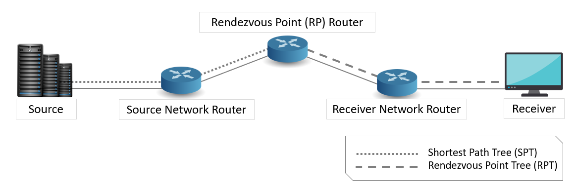
Figure 1‑2: Illustrates a PIM-enabled network with the routers
To configure PIM in NetSim
Create a network as shown below Figure 1‑3.

Figure 1‑3: Network Topology in this experiment
Set PIM status as TRUE in all routers as shown below:
Set IGMP status as true for all devices.

Figure 1‑4: Network layer window
Configure the PIM properties as per the below screenshot and click on Add.

Figure 1‑5: PIM Configuration window
Then click on Accept.
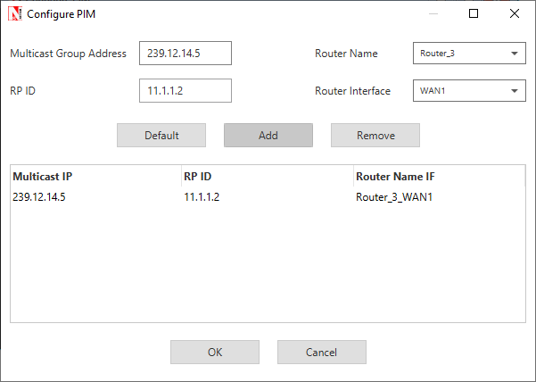
Figure 1‑6: Once PIM Configuration Done
Configure the same PIM properties for all routers in the network.
Application Properties:
Set the application properties as per the screenshot below – Multicast application with source 5 and destinations 6, 7, 8, 9, 10
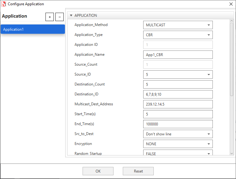
Figure 1‑7: Application properties window
Set IGMP_Status to TRUE in all wired nodes since we are running multicast application.
Enable packet Trace, Plots and run simulation for 10s. Open Packet trace and filter PACKET_ID to 1. Users can observe there is no formation of loops between source and destinations.

Figure 1‑8: Packet Trace
Access Control Lists (ACLs)#
Introduction#
Access Control Lists (ACLs) are filters that routers use to control which, routing updates, or packets are permitted or denied, in or out, of a network. An ACL contains a sequential list of “permit” or deny statements (rules) that apply to IP packets originating or destined to hosts, IP addresses and upper-layer IP protocols.
An ACL tells the router what types of packets to: permit or deny. The router using the ACL does the following when it finds packets inbound to or outbound from a network:
-
If the router finds packets inbound or outbound categorized against > the permit statements, the router forwards the packets to the next > hop in the network.
-
If the router finds packets inbound or outbound categorized against > the deny statements, the router blocks and drops the packets at > the router’s interface. The packets cannot reach the intended > destination host or IP address.
-
ACLs control traffic in one direction at a time, on an interface. To > allow inbound and outbound traffic from a host, IP address, or for > a protocol, you must create two ACLs, one for each direction, one > for inbound and one for outbound traffic.
-
The precedence of the ACL commands is from top to bottom.
For example, If ACL is configured in Router as follows:
PERMIT OUTBOUND TCP ANY ANY 0 0 3
PERMIT INBOUND TCP ANY ANY 0 0 3
DENY BOTH ANY ANY ANY 0 0 3
Then, the Permit statements will over-ride the deny statements. That is, Outbound TCP packets from Router through interface 3 will be permitted first, after that, the Inbound TCP packets to Router through interface 3 will be permitted. All other packets through the third interface of Router will be denied in both directions.
Virtual LAN (VLAN)#
Introduction#
VLAN is called as virtual local area network, used in Switches and it operates at layer2 and Layer3. A VLAN, is a group of hosts which communicate as if they were attached to the same broadcast domain, regardless of their physical location.
For example, all workstations and servers used by a particular workgroup team can be connected to the same VLAN, regardless of their physical connections to the network or the fact that they might be intermingled with other teams. VLANs have the same attributes as physical LANs, but you can group end stations even if they are not physically located on the same LAN segment.
A VLAN behaves just like a LAN in all respects but with additional flexibility. By using VLAN technology, it is possible to subdivide a single physical switch into several logical switches. VLANs are implemented by using the appropriate switch configuration commands to create the VLANs and assign specific switch interfaces to the desired VLAN.

Figure 3‑1: Virtual local area network (VLAN)
Switches implement VLANs by adding a VLAN tag to the Ethernet frames as they enter the switch. The VLAN tag contains the VLAN ID and other information, which is determined by the interface from which the frame enters the switch. The switch uses VLAN tags to ensure that each Ethernet frame is confined to the VLAN to which it belongs based on the VLAN ID contained in the VLAN tag. The VLAN tags are removed as the frames exit the switch on the way to their destination.
Any port can belong to a VLAN, and unicast, broadcast, and multicast packets are forwarded and flooded only to end stations in that VLAN. Each VLAN is considered a logical network. Packets destined for stations that do not belong to the VLAN must be forwarded through a router. In the below screenshot, the stations in the development department are assigned to one VLAN, the stations in the marketing department are assigned to another VLAN, and the stations in the testing department are assigned to another VLAN.
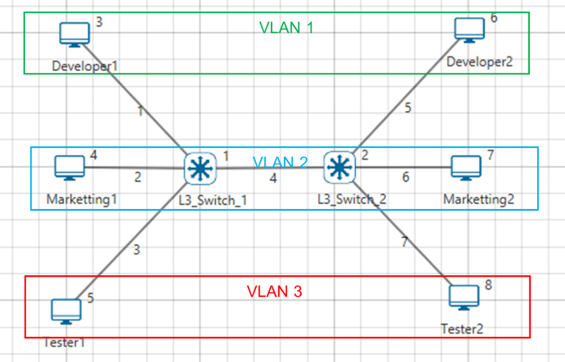
Figure 3‑2: Hosts in one VLAN need to communicate with hosts in another VLAN
When do we need a VLAN?#
You need to consider using VLAN’s in any of the following situations:
-
You have more than 200 devices on your LAN.
-
You have a lot of broadcast traffic on your LAN.
-
Groups of users need more security are being slowed down by too many > broadcasts.
-
Groups of users need to be on the same broadcast domain because they > are running same applications or just make a single switch into > multiple virtual switches.
VLAN ID#
VLANs are identified by a VLAN ID (a number between 0 – 4095), with the default VLAN on any network being VLAN 2. Each port on a switch or router can be assigned to be a member of a VLAN (i.e., to allow receiving and sending traffic on that VLAN).
For example: On a switch, traffic that is sent to a port that is a member of VLAN2, may be forwarded to any other VLAN2 port on the switch, and it can also travel across a trunk port (connections between switches) to another switch and forwarded to all VLAN2 ports on that switch. Traffic will not be forwarded to ports that are on a different VLAN ID.

Figure 3‑3: Understanding Access and Trunk Links
Understanding Access and Trunk Links#
The links connecting the end devices are called access links. These are the links usually carrying the Data VLAN information
The link between the switches is called trunk link. It carries packets from all the VLANs.
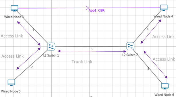
Figure 3‑4: Understanding Access and Trunk Links
Access Link#
Access link connection is the connection where switch port is connected with a device that has a standardized Ethernet NIC. Standard NIC only understand IEEE 802.3 or Ethernet II frames. Access link connection can only be assigned with single VLAN. That means all devices connected to this port will be in same broadcast domain.
For example, twenty users are connected to a hub, and we connect that hub with an access link port on switch, then all of these users belong to same VLAN. If we want to keep ten users in another VLAN, then we need to plug in those ten users to another hub and then connect it with another access link port on switch.
Trunk Link#
Trunk link connection is the connection where switch port is connected with a device that is capable to understand multiple VLANs. Usually trunk link connection is used to connect two switches. Trunking allows us to send or receive VLAN information across the network. To support trunking, original Ethernet frame is modified to carry VLAN information.
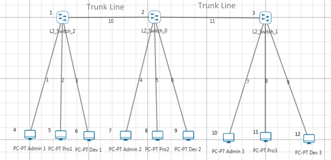
Figure 3‑5: Understand multiple VLANs
Public IP Address & NAT (Network Address Translation)#
Introduction#
Public Address#
A public IP address is assigned to every computer that connects to the Internet where each IP is unique. Hence there cannot exist two computers with the same public IP address all over the Internet. This addressing scheme makes it possible for the computers to “find each other” online and exchange information. User has no control over the IP address (public) that is assigned to the computer. The public IP address is assigned to the computer by the Internet Service Provider as soon as the computer is connected to the Internet gateway.
Private Address#
An IP address is considered private if the IP number falls within one of the IP address ranges reserved for private networks such as a Local Area Network (LAN). The Internet Assigned Numbers Authority (IANA) has reserved the following three blocks of the IP address space for private networks (local networks):
| Class | Starting IP address | Ending IP address | No. of hosts |
|---|---|---|---|
| A | 10.0.0.0 | 10.255.255.255 | 16,777,216 |
| B | 172.16.0.0 | 172.31.255.255 | 1,048,576 |
| C | 192.168.0.0 | 192.168.255.255 | 65,536 |
Table 4‑1: Private IP address table
Private IP addresses are used for numbering the computers in a private network including home, school and business LANs in airports and hotels which makes it possible for the computers in the network to communicate with each other. For example, if a network A consists of 30 computers each of them can be given an IP starting from 192.168.0.1 to 192.168.0.30.
Devices with private IP addresses cannot connect directly to the Internet. Likewise, computers outside the local network cannot connect directly to a device with a private IP. It is possible to interconnect two private networks with the help of a router or a similar device that supports Network Address Translation.
If the private network is connected to the Internet (through an Internet connection via ISP) then each computer will have a private IP as well as a public IP. Private IP is used for communication within the network whereas the public IP is used for communication over the Internet.
Network address translation (NAT)#
NAT (Network Address Translation or Network Address Translator) is the virtualization of Internet Protocol (IP) addresses. NAT helps to improve security and decrease the number of IP addresses an organization needs.
A device that is configured with NAT will have at least one interface to the inside network and one to the outside network. In a typical environment, NAT is configured at the exit device between a stub domain (inside network) and the backbone. When a packet leaves the domain, NAT translates the locally significant source address into a globally unique address. When a packet enters the domain, NAT translates the globally unique destination address into a local address. If more than one exit point exists, each NAT must have the same translation table. NAT can be configured to advertise to the outside world only one address for the entire network. This ability provides additional security by effectively hiding the entire internal network behind that one address. If NAT cannot allocate an address because it has run out of addresses, it drops the packet and sends an Internet Control Message Protocol (ICMP) host unreachable packet to the destination.
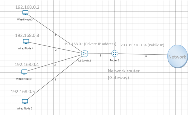
Figure 4‑1: NAT implementation
NAT is secure since it hides network from the Internet. All communications from internal private network are handled by the NAT device, which will ensure all the appropriate translations are performed and provide a flawless connection between internal devices and the Internet.
In the above figure, a simple network of 4 hosts and one router that connects this network to the Internet. All hosts in the network have a private Class C IP Address, including the router's private interface (192.168.0.1), while the public interface that's connected to the Internet has a real IP Address (203.31.220.134). This is the IP address the Internet sees as all internal IP addresses are hidden.
Advanced Routing Experiments in NetSim#
Apart from examples, in-built experiments are also available in NetSim. Examples help the user understand the working of features in NetSim. Experiments are designed to help the user (usually students) learn networking concepts through simulation. The experiments contain objective, theory, set-up, results, and inference. The following experiments are available in the Experiments manual (pdf file).
-
Understanding VLAN operation in L2 and L3 Switches
-
Understanding Access and Trunk Links in VLANs
-
Understanding Public IP Address & NAT (Network Address Translation)
-
Understand the working of basic networking commands (Ping, Route Add/Delete/Print, ACL)
Reference Documents#
-
IEEE802.1Q for Virtual LAN
-
IETF 7761 for Protocol Independent Multicast – Sparse Mode (PIM-SM)
-
RFC 2236 for Internet Group Management Protocol, Version 2
Latest FAQs#
Up to date FAQs on NetSim’s Advance Routing library is available at
https://tetcos.freshdesk.com/support/solutions/folders/14000113123