Multicast Routing Protocols Example #
IGMP Example#
This example explains how IGMP works to multicast data in interconnected networks.
The network modelled consists of:
-
A subnet with 4 wired nodes, a multicast router, and a multicast > application running on one of the wired nodes.
-
IGMP is running on all the wired nodes.
-
IGMP is running on the multicast router.
-
Only a few nodes receive multicast traffic.
NetSim uses the following defaults for IGMP simulations:
-
The multicast destination address is set to 239.12.14.5.
-
The IGMP protocol starts only after 1 second into the simulation.
-
The multicast application starts only after 5 seconds into the > simulation.
Note that NetSim does not support the following in IGMP:
-
Leave Group message
-
IGMP v1 compatibility
Open NetSim, Select Examples->Advanced Routing->Multicasting with IGMP then click on the tile in the middle panel to load the example as shown in Figure 5‑1.
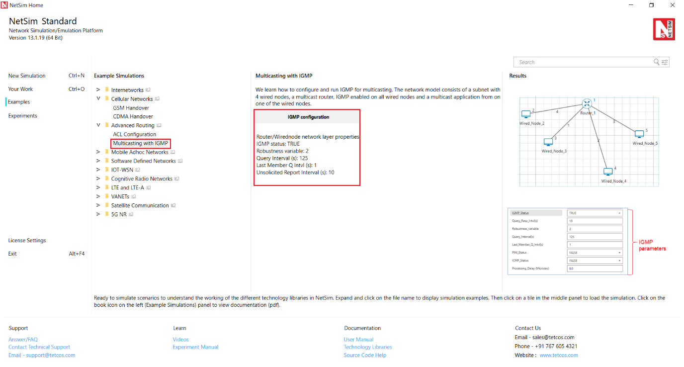
Figure 5‑1: List of scenarios for the example of IGMP Configuration
The following network diagram illustrates what the NetSim UI displays when you open the example configuration file for IGMP Figure 5‑2.

Figure 5‑2: Network set up for studying the IGMP Configuration
-
See that by default, NetSim has enabled IGMP on the router, as follows:
- Right-click the router and click Properties.
The Router pop-up window appears.
-
Click NETWORK LAYER in the left area.
-
IGMP_Status drop-down list is set to TRUE.
-
Click OK.
-
See that by default, NetSim has enabled IGMP on a node, as follows:
- Right-click a wired node (say Wired_Node_2) and click > Properties.
The Wired node pop-up window appears.
-
Click NETWORK LAYER in the left area.
-
IGMP_Status drop-down list is set to TRUE.
The Wired node pop-up window displays the following parameters you can configure for IGMP, on the node:
-
Robustness_variable: The Robustness_variable parameter allows > you tune your subnet to a specific number of lost packets (packet > loss) in the subnet.
-
Query_Interval(s): The Query_Interval(s) parameter allows you to > specify the interval (in seconds) between two successive General > Queries that a Querier multicast router sends.
-
Last_Member_Q_Intvl(s): The Last_Member_Q_Intvl(s) parameter > allows you specify the interval (in seconds) between two > successive Group-Specific Query messages that a multicast router > sends to hosts.
-
Unsol_Report_Intvl(s): The Unsol_Report_Intvl(s) is the time > between repetitions of a host’s initial report of membership in a > group.
The following image illustrates the wired node pop-up window and the parameters you can configure for IGMP, on the node.
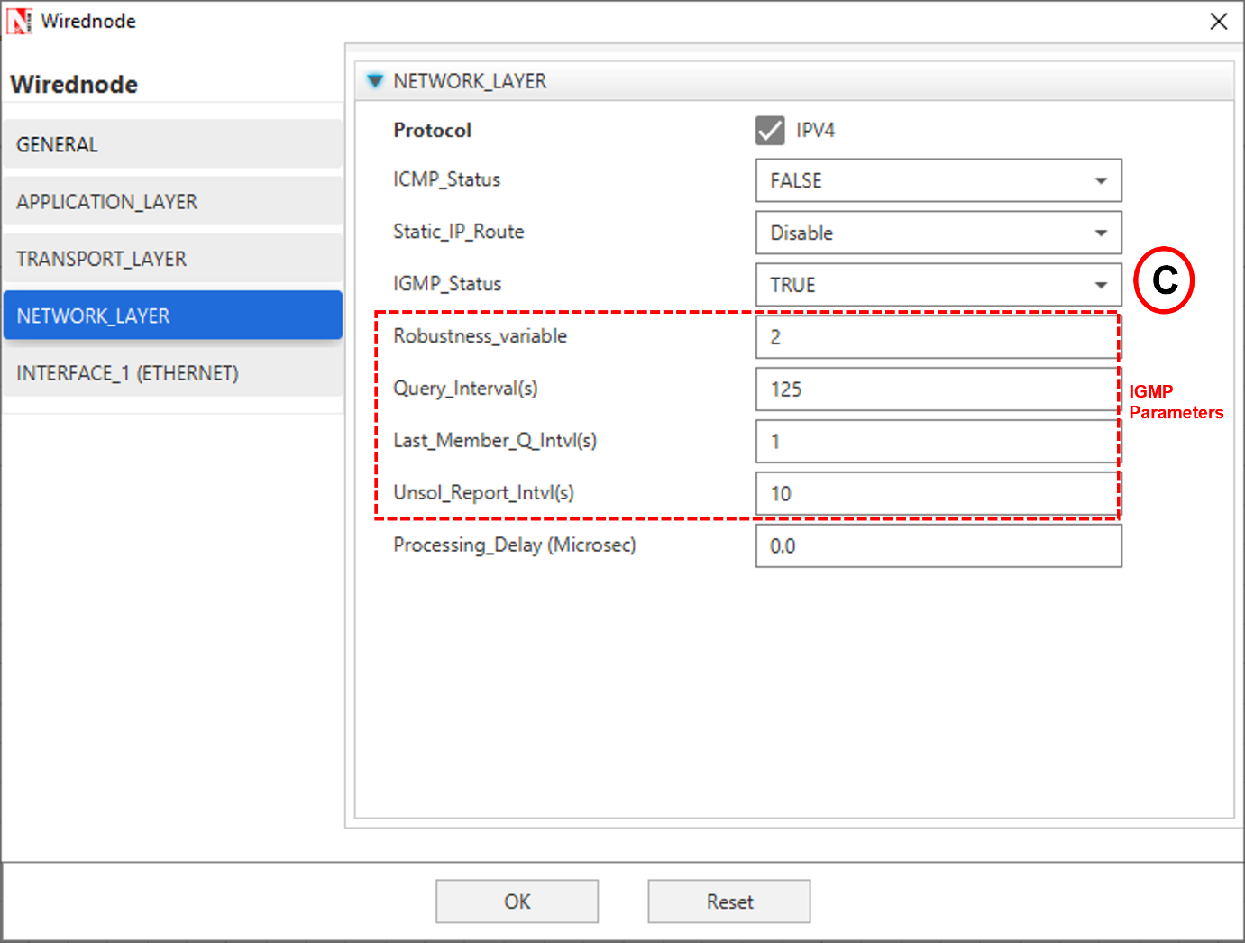
Figure 5‑3: Network layer IGMP Properties
- Click OK.
-
(Optional) Do the following to modify the parameters of IGMP.
-
To modify the value of the Robustness_variable, enter a value in the > Robustness_variable text box.
The default value of the Robustness_variable parameter is 2.
You can enter a value between 2 and 10.
NetSim does not allow you to enter a value that is less than 2. If you enter a value that is less than 2, NetSim resets the value to 2.
Increase the value of the Robustness_variable to more than 2, if you want to simulate a subnet that must lose more packets.
By default, IGMP is robust to (Robustness Variable-1) packet losses.
- To modify the value of the Query_Interval(s), enter a value in > seconds, in the Query_Interval(s) text box.
The default value of the Query_Interval(s) parameter is 125 seconds.
You can enter a value between 1 and 3600 seconds.
Fine-tune the Query_Interval(s) parameter to control the number of IGMP messages on the subnet.
- To modify the value of the Query_Interval(s), enter a value in > seconds, in the Last_Member_Q_Intvl(s) text box.
The default value of the Last_Member_Q_Intvl(s) parameter is 1 second.
You can enter a value between 1 and 25 seconds.
Fine-tune the Last_Member_Q_Intvl(s) parameter to make your subnet less or more busty of IGMP messages.
- To modify the value of the Query_Interval(s), enter a value in > seconds, in the Unsolicited_Report_Interval(s) text box.
The default value of the Last_Member_Q_Intvl(s) parameter is 10 seconds.
Fine-tune the Unsolicited_Report_Interval(s) parameter to make your subnet less or more busty of IGMP messages.
You can enter a value between 1 and 10,000 seconds.
-
Repeat steps 3 on other nodes to see that NetSim has enabled IGMP and step 4 on other nodes, if you to modify the IGMP parameters.
-
To configure a multicast application:
- Click the Application icon located in the toolbar.
The Application pop-up window appears.
- See that by default, NetSim has set the following properties for the > multicast application:
-
Application_Method = MULTICAST.
-
Source_ID = 2, which means Wired_Node_2 node is the > source of the application and the multicast traffic.
-
Destination_Count = 2, which means two nodes will receive > multicast traffic from the multicast application.
-
Destination_ID = 3, 4, which means, Wired_Node_3 and > Wired_Node_4 nodes must receive multicast traffic from the > multicast application.
-
Set application start time to 5s.
- (Optional) Modify the properties except (i).
Note: You add more than one destination IDs, by separating two successive numbers by a “,” (comma). The following image illustrates the properties of the multicast application as shown Figure 5‑4.

Figure 5‑4: Application Properties window
- Click OK.
-
See that by default, NetSim has enabled the Packet Trace, Event Trace and Plots icons located in the toolbar.
-
To start and run the simulation:
-
Click the Run icon located in the toolbar.
-
Enter a numerical value in the Simulation Time text box, say > 50s.
-
Click OK.
-
NetSim simulates IGMP for the time set.
Results#
After NetSim simulates IGMP, a Simulation Results window appears.
You can do the following on this window:
-
Print the results that NetSim displays in the Simulation Results > window.
-
View the packet trace details in a .CSV file and save the .CSV > file to your computer.
-
View the event trace details in a .CSV file and save the .CSV > file to your computer.
-
Export the results that NetSim displays in the Simulation Results > window, in a spreadsheet.
-
Close the Simulation Results window and return to your simulation.
NetSim also saves the last instance of your simulation for you to view, analyse, and download the results.
Interpreting the IGMP Simulation
Before you analyse the packet trace and event trace results, we recommend that you first interpret how IGMP worked with the parameters you specified. So, you must first view the simulation.
To view and interpret the simulation:
-
Close the Simulation Results window and return to your simulation.
-
Click the View Animation icon located on the toolbar.
The NetSim Packet Animation window appears.
- Click the Play icon located on the toolbar.
You will see that the simulation runs IGMP.
The details of the packet traversing in your network appear as table located below the simulation window.
- (Optional) To fine-tune the speed of the animation, use the Animation Speed slider located on the toolbar.
You will see the following happen in the animation:
-
Initially, all nodes (Wired_Node_2, 3, 4 and 5) receive the > IGMP_Memebership_Query message from Router_1.
-
When a node receives the IGMP_Memebership_Query message, the node > sends the IGMP_V2_Membership_Report to Router_1 indicating that it > is interested to join the multicast group.
You can see that Wired_Node_3 sends the IGMP_V2_Membership_Report message to Router_1. Wired_Node 2, 4 and 5 also send the IGMP_V2_Membership_Report message to Router_1.
- Router_1 makes an entry for the membership in its routing table.
The following image illustrates IGMP at work.

Figure 5‑5: Packet animation window
When NetSim completes the simulation, the Simulation Results window appears.
Analyzing the Packet Trace Results
Now that you have seen the simulation for IGMP, we will analyze the communication between the nodes and the router.
To view and analyze the packet trace results:
- On the Simulation Results window, click Open Packet Trace located in the left area.
A .CSV appears.
- Open the .CSV file and filter the PACKET_ID column by 0 and 1.
You will see the following in the .CSV file.
-
Router_1 broadcasts the IGMP_Memebership_Query message to all the > nodes.
-
When a node receives the IGMP_Memebership_Query message, the node > sends the IGMP_V2_Membership_Report message to the Router_1.
-
The IGMP protocol starts to work only after 1 second in to the > simulation.
The following image illustrates (i), (ii), and (iii).

Figure 5‑6: IGMP_Memebership_Query messages in Packet trace
- The multicast application Wired_Node_2 starts to send multicast > traffic to Wired_Node_3 and Wired_Node_4 only after 5 seconds in > to the simulation.
This is because, in NetSim, the multicast application starts after 5 seconds by default.
- Wired_Node_2 multicasts Constant Bit Rate (CBR) packets only to > Wired_Node_3 and Wired_Node_4.
The following image illustrates (iv), and (v).

Figure 5‑7: Node 2 multicasting CBR packets to other Nodes
- Hosts send the IGMP_V2_Membership_Report to 224.0.0.1 to the > multicast application sends multicast traffic to 239.12.14.5.
The following image illustrates (vi).

Figure 5‑8: IGMP_V2_Membership_Report to 224.0.0.1 in packet trace
IGMP Event Trace Analysis
Now that you have seen the results of packet trace, we will analyze the event trace for this IGMP simulation.
To view the event trace results:
-
On the Simulation Results window, click Open Event Trace located in the left area.A .CSV appears.
-
Open the .CSV file and filter the Event_Type column by NETWORK_OUT and TIMER_EVENT.
You will see the following sub-events in the Subevent_Type column:
-
IGMP_DelayTimer: This sub-event occurs when a node sets the delay > timers for every group (excluding the all-systems group) to which > the node belongs, on the interface on which it received the query, > after the node receives a General Query from the multicast router.
-
IGMP_GroupMembershipTimer: This sub-event occurs when the > multicast router refreshes the group membership interval timer, > every time it receives a membership report for a multicast group. > If this timer expires, the multicast router removes this group > from the list of destinations for multicast traffic.
-
IGMP_SendQuery: This sub-event occurs when the multicast router > periodically (based on Query Interval) sends a Query message on > every network to which the multicast router is connected, to > solicit multicast group membership information.
-
IGMP_SendStartupQuery: This subevent occurs when the multicast > router sends the Startup query count to quickly and reliably > determine the multicast group membership information, at startup.
-
IGMP_UnsolicitedReportTimer: If the initial membership report is > lost or damaged, this timer repeats once or twice after short > delays, after every Unsolicited Report Interval.
-
JOIN_MULTICAST_GROUP: This sub-event occurs when a node sends > the join multicast group message, when the node decides to join a > multicast group on an interface.
In NetSim, a node joins a multicast group only after 5 seconds into the simulation.
The following image illustrates that hosts join the multicast group after 5 seconds.

Figure 5‑9: Node joins a multicast group
Access Control Lists (ACLs) Examples #
ACL Example#
This example models a network and simulates an ACL to understand how ACL filters inbound and outbound traffic at a router’s interface.
The network modelled consists of:
-
Two subnets with 2 wired nodes, 1 router each and 3 applications.
-
ACLs with both permit and deny rules are defined on the interfaces > of the router.
NetSim uses the following directions for ACL simulations:
-
The direction of the ACL is set to both. This means the ACL applies > to both inbound and outbound traffic.
-
The direction of ACL is set to Inbound. This means the ACL applies > to inbound traffic only.
-
The direction of ACL is set to Outbound. This means the ACL applies > to outbound traffic only.
Open NetSim, Select Examples->Advanced routing->ACL Configuration then click on the tile in the middle panel to load the example as shown below in Figure 5‑10.

Figure 5‑10: List of scenarios for the example of ACL Configuration
The following network diagram illustrates what the NetSim UI displays when you open the example configuration file for ACL as shown Figure 5‑11.

Figure 5‑11: Network set up for studying the ACL Configuration
- ACL enabled in Network Layer of Router_5 and were configured as follows as shown Figure 5‑12.

Figure 5‑12: ACL Configuration for Router 5
- ACL enabled in Network Layer of Router_6 and were configured as follows as Figure 5‑13.

Figure 5‑13: ACL Configuration for Router 6
-
Transport protocol set as UDP for APP_1_CBR and APP_3_CBR.
-
Transport protocol set as TCP for APP_2_CBR.
-
Enable the plots and run Simulation for 10 seconds and observe the throughput obtained for the three applications.
Result and Observations#

Figure 5‑14: Application Metrics Table in result window
The throughput for first application is zero, since the ACL blocks OUTBOUND UDP traffic flow in Router_5 from Wired Node 2 to Wired Node 1
The throughput for second application is non-zero, since the ACL ‘Permits’ TCP traffic flow in Router_5 and Router6 from Wired Node 1 to Wired Node 3.
The throughput for the third application is non-zero as ACL ‘Permits’ UDP traffic flow in Router_6 from Wired_Node_4 to Wired_Node_2.