Lab Set-up
In this section we discuss how to set up your lab to perform attacks on communication network with real devices connected on a live network.
Network Setup
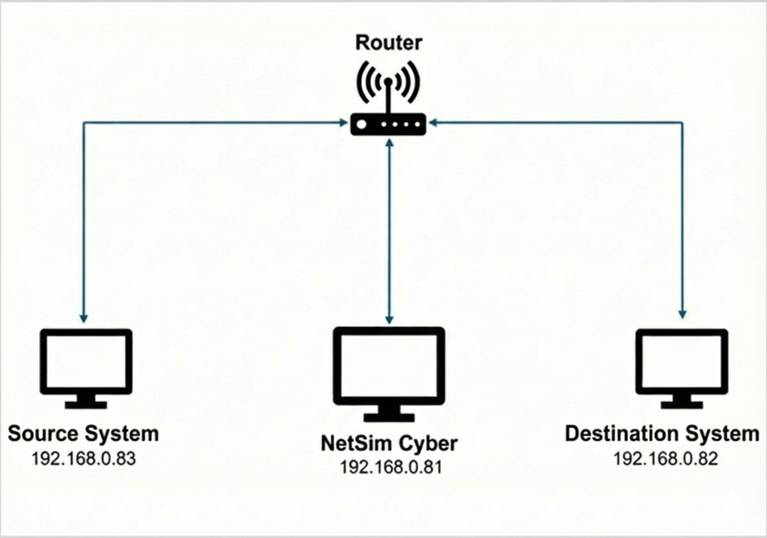
This network setup consists of three systems: Source, Destination, and the NetSim Cyber system, which serves as the gateway. In this example:
Source System: IP address – 192.168.0.83. This system runs a client program to communicate with the server. Typically, in a use-case this can be the system/IP enabled device generating data and transmitting to its server or destination node. For example, in RTDS with communication module, PMU will be client sending Synchro phasor data can be considered as Client system which connects to PDC.
NetSim Cyber: 192.168.0.81. It emulates a network environment, enabling communication between the client and server. Data flows through the network created in NetSim.
Destination System: 192.168.0.82. This system runs a server program that connects to the source. Typically, in a use-case this can be the system/device which receives the data sent from the client or source node. For example, PDC which receives the data from the PMU is considered as Server System.
Steps to Set Up Source/Client and Destination/Server System
Method 1: Manual Route Configuration
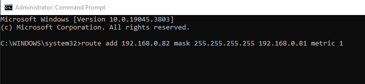
1. Source system (192.168.0.83)
To add a static route, you’ll need to open the command prompt in administrator mode. Once open, input the following command:
route add <Destination IP address> mask <Subnet mask> <Gateway IP address> metric 1
Replace <Destination IP address> with the IP
address of the destination system, <Subnet mask> with
the appropriate subnet mask, and <Gateway IP address>
with the IP address of the gateway. This command will effectively add
the static route.
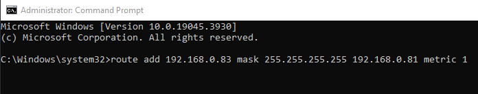
2. Destination system (192.168.0.82)
To facilitate communication for TCP traffic, it’s essential to configure a reverse route on the destination system as well.
route add <IP address of Destination system> mask <Subnet mask> <Gateway IP address> metric 1
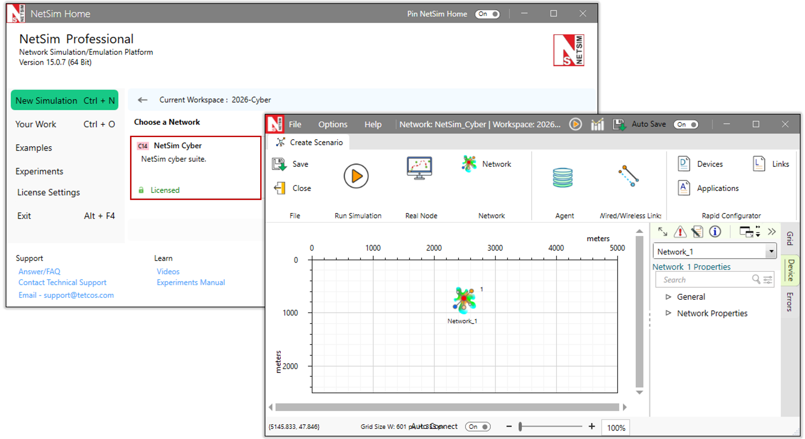
Method 2: Automatic Configuration using NetSim Cyber Client
As an alternative to manually configuring routes on the source and destination systems, users can utilize the NetSimCyberClient.exe utility to automate the process.
Prerequisites: Before proceeding, ensure the NetSim Cyber Suite UI is running on the gateway system (192.168.0.81)
Steps:
Place the NetSimCyberClient.exe utility on both the Source/Client system (192.168.0.83) and the Destination/Server system (192.168.0.82).
Run the NetSimCyberClient.exe as run as administrator on both systems.
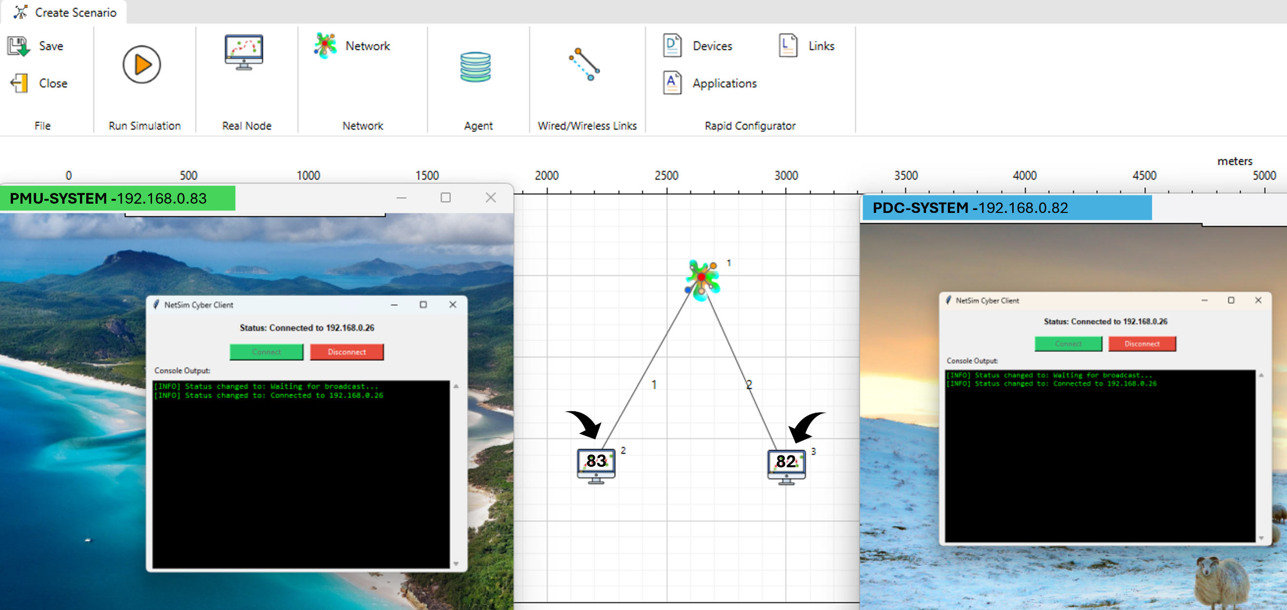
Upon running the utility, the nodes will automatically be dropped into the NetSim environment, as seen in the above example layout where distinct nodes connect to the central network cloud. The routing tables on the client and server systems will be updated automatically to direct traffic through the NetSim gateway.
How it works:
When the NetSim Cyber tile starts on the gateway system, it begins broadcasting a message containing its IP address across the entire network on port 19001 every second.
NetSimCyberClient utility runs on the client or server system, it starts listening for these broadcast messages on port 19001.
Upon receiving a message from the network on this port, the utility establishes a connection with the NetSim system.
It then automatically alters the local route table so that packets are transmitted through the system running NetSim.
Finally, it starts sending packets containing its own IP address and Device Name to NetSim. When NetSim receives these packets on port 19001, it reads the information and automatically drops a device node with the respective IP address and Device Name into the simulation scenario.