Common Network Attack Scenarios
NetSim Experiment Setup
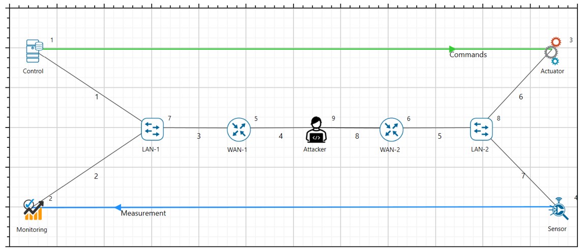
For the common network attacks discussed in the manual, all will have a fixed setup in NetSim as shown in the figure below.

Network Topology:
Control Centre: Central node responsible for managing and monitoring the CPS.
Field Devices (Sensors/Actuators): Nodes that provide data and execute control commands.
Communication Links: Network connections between the control center and field devices, configured to simulate packet drops.
Attacker Node: This will be added in each attack based on the attack type.
Delay Attack
Deterministic Delay Attack in Communication Link
Abstract
In NetSim, an attacker exploits the deterministic delay in the communication links used for time synchronization. By introducing a subtle but consistent delay, the attacker can disrupt the time synchronization process, causing desynchronization among devices in the CPS. This can lead to inaccurate data reporting, improper load balancing, and even failures in automated control mechanisms.
Note: To perform deterministic delay attack in NetSim, there are no changes to code or scripts to be run. This can be performed within NetSim UI.
Objective
In this experiment there are mainly 2 parts where an attacker exploits the deterministic nature of this delay by performing a timing attack in the (a) Links and (b) Devices:
By performing simulation in NetSim. Here the data transferred between legitimate source and destination is virtual data generated by NetSim.
By performing emulation in NetSim. Here the data between legitimate source and destination are generated by real devices by running python scripts/real application to generate real-data and transmitted over electrical protocol via NetSim.
Parameters and Settings
In the network setup, all the node parameters remain unchanged except the name of the node.
Set the traffic to a desired rate since we are not focusing here on the data rate.
Configure Deterministic Delay attack: Introduce Malicious Router:
Add an attacker node to the network such that the CPS devices communicate over the attacker node as shown in the figure below.
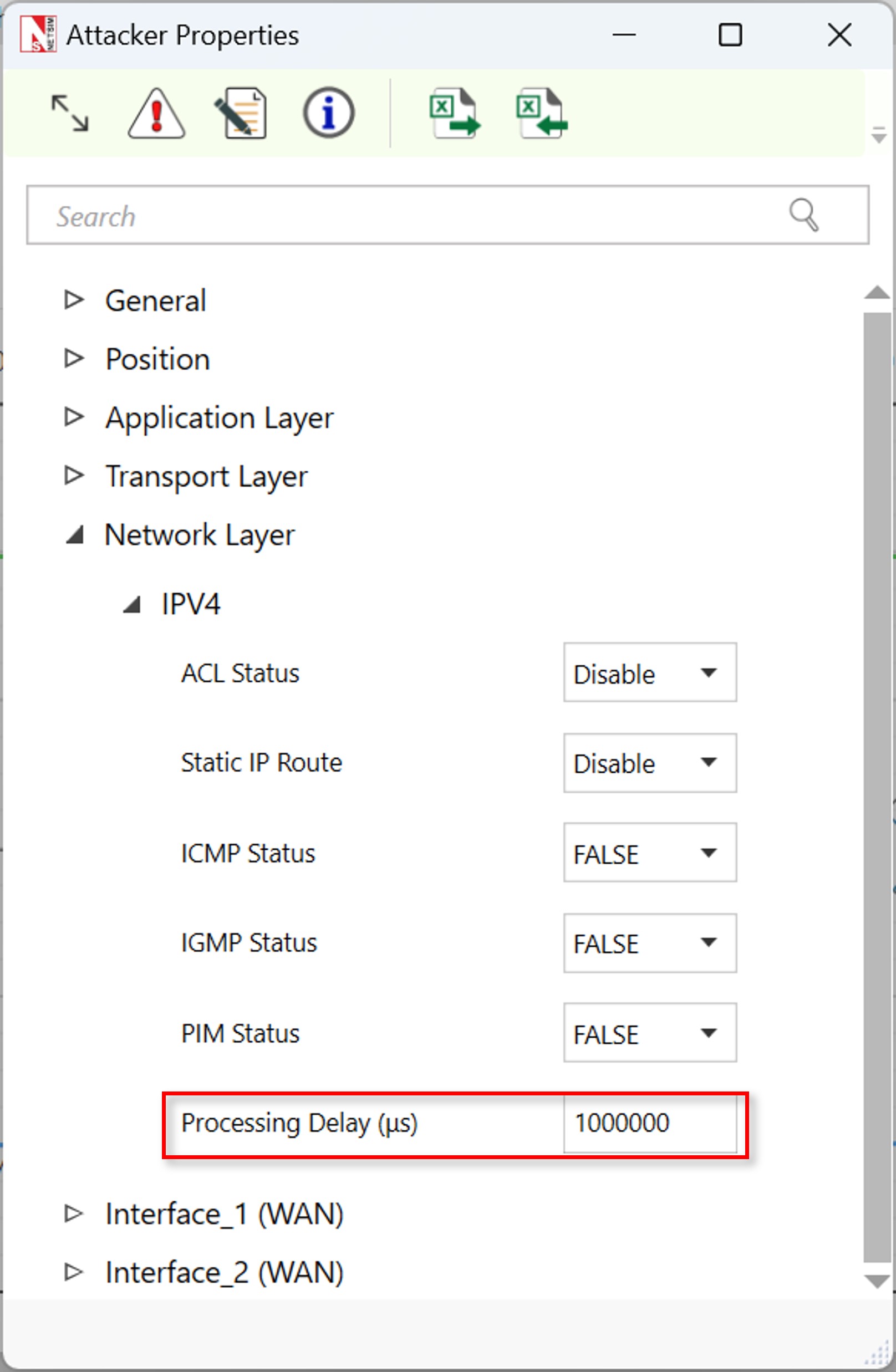
Add an additional Processing delay in the node (e.g., an extra 1s).
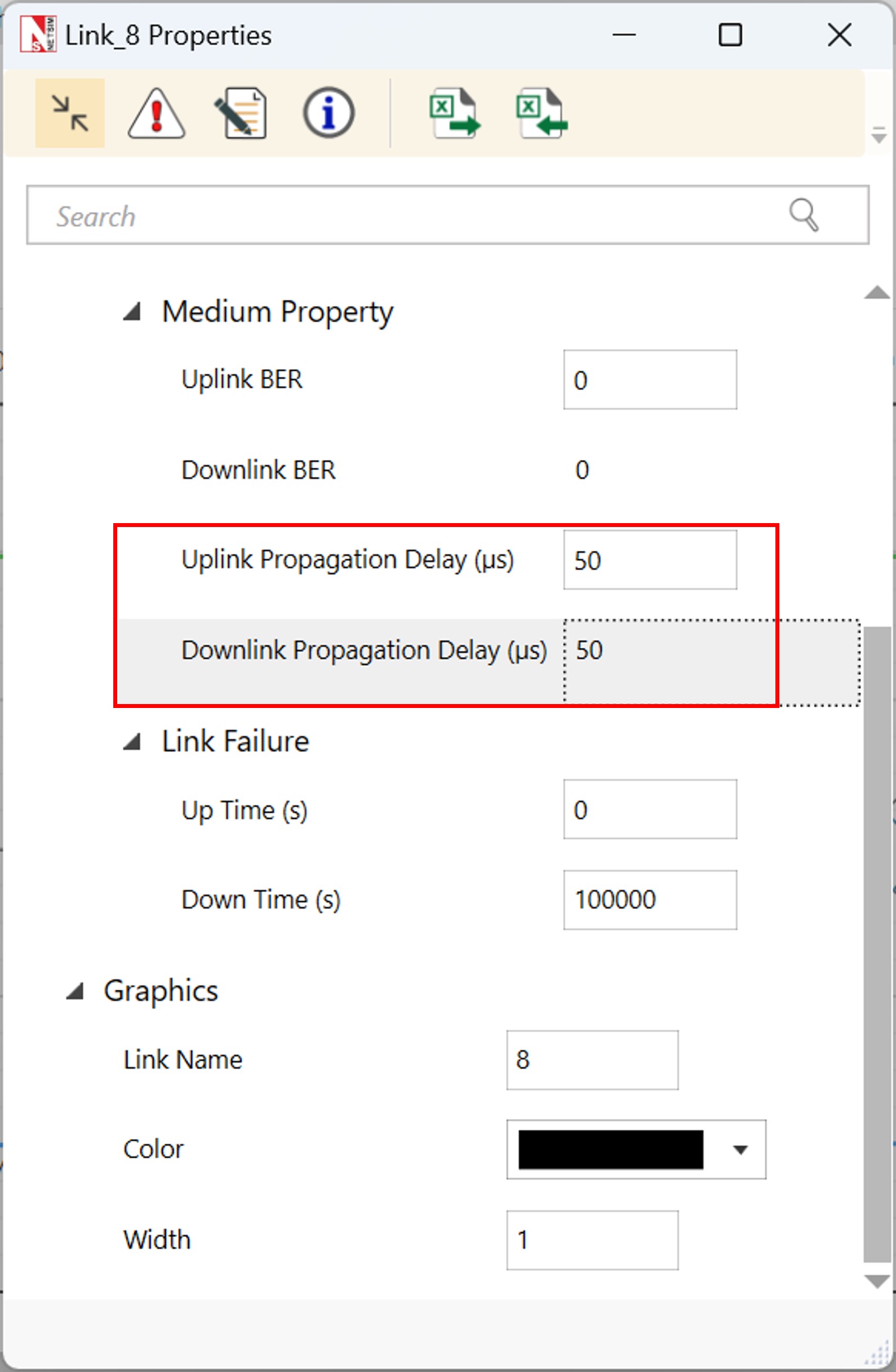
Add an additional propagation delay in the links where router is connected to the attacker node.
Step-by-step Procedure
We have shared the sample file, where users can download and import where NetSim is installed.
The procedure to download and import to NetSim is given in the last section of this manual.
Results and Analysis
Once you import the experiment, open and run the sample.
You will observe the additional deterministic delay in the results dashboard.


Stochastic Delay Attack in Communication Link
Abstract
In NetSim, an attacker exploits the stochastic nature of delays in communication links used for time synchronization. By introducing subtle, random delays, the attacker can disrupt the time synchronization process, causing desynchronization among devices in the CPS. This can lead to inaccurate data reporting, improper load balancing, and failures in automated control mechanisms.
Note: To perform stochastic delay attack in NetSim, we have performed changes to code to run this attack to randomize the delay. Users will require Standard version of NetSim.
Parameters and Settings
In the network setup, all the node parameters remain unchanged except the name of the node. And all the settings are per Deterministic delay attack scenario.
Code Changes
The given function below will be used for adding random delay in the attacker node as a processing delay.
long int stochastic_delay(unsigned int seed) {
    int delay = rand() % 1000 + 1; // Generate a random delay
                                    // between 1 and 1000 microseconds
    return(delay);
}
Results and Analysis
Once you import the experiment, open and run the sample.
You will observe the additional stochastic delay in the results dashboard.

Communication Link Failure Attack (TCP and UDP)
Objective
The experiment aims to simulate and analyse the effects of communication link failures on both TCP and UDP protocols within a Cyber-Physical System (CPS). The experiment will highlight the differences in how these protocols handle link failures and the resulting impact on system operations.
Note: To perform this attack in NetSim, there are no changes to code or scripts to be run. This can be performed within NetSim UI.
Experiment Setup

Control Center: Central node for monitoring and controlling the CPS.
Field Devices (Sensors/Actuators): Nodes that collect data and execute control commands.
Communication Links: WAN connections between the control center and field devices, using both TCP and UDP protocols.
Attacker Node: Node configured to simulate communication link failures.
Procedure
Setting Up the Network:
Define the CPS network environment.
Add and Configure Nodes:
Control Center: Add as the central server node.
Field Devices: Add nodes representing sensors and actuators.
Attacker Node: Include a node to simulate communication disruptions.
Establish Communication Links.
Protocol Configuration:
TCP Configuration: Configure TCP links to prioritize reliability, setting appropriate parameters for window size, acknowledgment, and retransmission.
UDP Configuration: Configure UDP links for minimal latency, focusing on packet delivery without guarantee of order or reliability.
Simulating Communication Link Failures
Normal Operation Phase
Run the simulation under normal conditions to establish a baseline for TCP and UDP communication.
Introduce Link Failures: TCP Application
Set the application Transport Layer protocol to TCP.
In the links that are connected to the attacker node, configure link failure duration.

UDP Link Failures
Similarly, configure the UDP as Transport Layer Protocol in the application properties.
Similar adjustment for failure parameters to observe the impact on UDP traffic.
Results
Normal Operation Phase

Communication Link Failure for TCP Traffic


Communication Link Failure for UDP Traffic

Denial-of-Service (DOS) Attacks and DDoS
Data Flooding Attack
Objective
The goal of this experiment is to simulate a data flooding attack in a Cyber-Physical System (CPS) using NetSim. This experiment aims to demonstrate the impact of excessive data traffic on the performance and reliability of the CPS, highlighting potential vulnerabilities.
Note: To perform data flooding attack in NetSim, there are no changes to code or scripts to be run. This can be performed within NetSim UI.
Setting Up the Network
Define the simulation environment to reflect a CPS setup.
Add and Configure Nodes:
Control Center: Add a node to represent the main server.
Field Devices: Add nodes representing various sensors and actuators in the CPS.
Attacker Node: Include a node to simulate the data flooding attack.
Connect the control center to the field devices using WAN links.
Configure the communication links with standard parameters (bandwidth, delay, etc.)
Simulating Data Flooding Attack in the CPS Network
Configuring Normal Operation:
Normal Traffic Configuration
Set up regular data traffic patterns between field devices and the control center.
Define normal packet sizes and inter-packet arrival times for both sensors (sending data) and actuators (receiving commands).
Baseline Measurement:
Run a simulation to establish baseline performance metrics, including latency, throughput, and error rates under normal traffic conditions.
Running the Attack Simulation
Start the simulation with the deactivated attacker node.
Monitor the network for signs of congestion, such as latency, packet loss, and throughput.
Simulating the Data Flooding Attack:
Attack Configuration
The attacker node has to generate a high volume of traffic, targeting the communication links. Configure the attacker node to send large packets at a high frequency, overwhelming the network.
Flooding Parameters:
Set parameters such as packet size and inter-packet arrival time to maximize congestion. Optionally, vary these parameters to observe the effects of different levels of flooding intensity.
Running the Attack Simulation
Start the simulation with the attacker node active.
Monitor the network for signs of congestion, such as increased latency, packet loss, and reduced throughput.
Results
Healthy traffic without data flood attack for both TCP and UDP:

Data flooding attack for random 5s interval for UDP traffic:


Probabilistic Packet Drop Attack
Objective
The objective of this experiment is to simulate the impact of probabilistic packet drops in the communication links of a Cyber-Physical System (CPS) using NetSim. The experiment aims to demonstrate how random packet losses can affect the reliability and performance of the system, and how different protocols handle these losses.
Note: To perform probabilistic packet drop attack in NetSim, there are no changes to code or scripts to be run. This can be performed within NetSim UI.
Network Topology

Setting Up the Network
Set up the CPS environment by defining the nodes and their roles.
Add and Configure Nodes:
Control Center: Add and configure as the central server.
Field Devices: Add sensors and actuators, configuring them to communicate with the control center.
Attacker Node (optional): If including an attacker node, configure it to simulate conditions leading to packet drops.
Connect the control center to the field devices using WAN links.
Set up the links for both TCP and UDP traffic, as applicable.
Simulating Probabilistic Packet Drop Attack in the CPS Network
Configuring Normal Operation:
Baseline Configuration
Set up normal communication conditions, defining regular packet sizes and inter-packet intervals for data transmission.
Run a preliminary simulation to establish baseline metrics such as latency, throughput, and packet delivery ratio.
Introducing Probabilistic Packet Drops:
Setting Up Packet Drop Conditions
Configure the communication links to introduce probabilistic packet drops.
Specify the probability of packet drops (e.g., 5%, 10%) to simulate different levels of network unreliability.
If using an attacker node, program it to generate conditions that lead to packet drops, mimicking a denial-of-service or interference attack.
Protocol-Specific Configurations:
TCP: Set parameters that allow TCP to handle packet drops, such as retransmission timeouts and congestion control settings.
UDP: Since UDP does not handle packet recovery, observe the direct impact of packet loss on data delivery.
Running the Simulation
Start the simulation with the packet drop conditions in place.
Monitor the network for performance changes, including increased latency, reduced throughput, and changes in packet delivery ratios.
Result Analysis
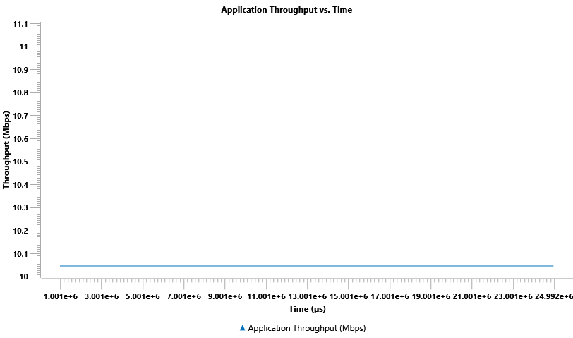
Normal Operation:

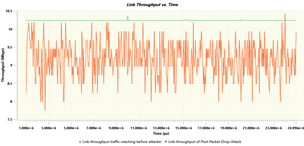
Probabilistic packets drop attack on a TCP based command traffic:

Probabilistic packets drop attack on a UDP based command traffic: