Simulation GUI
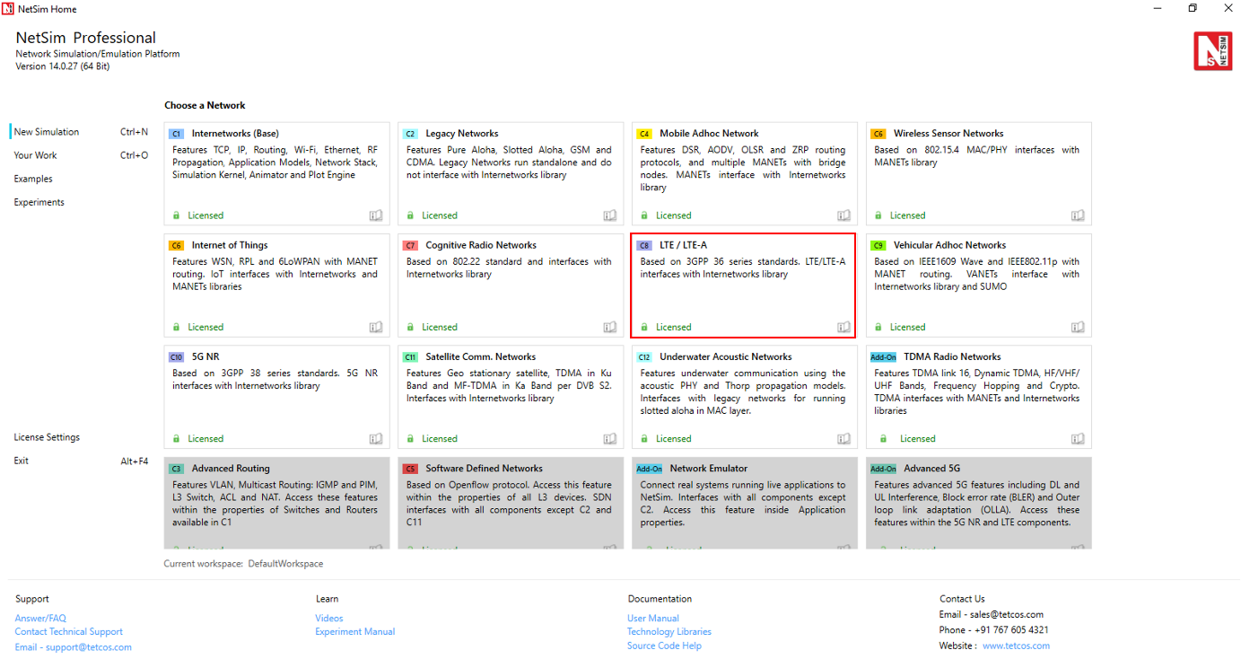
Open NetSim, Go to New Simulation \(\rightarrow\) LTE/LTE-A Networks
Create Scenario
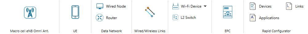
LTE comes with a palette of various devices like Wired & Wireless Nodes, L2 Switch & Access Point, EPC (Evolved Packet Core) & Router, Macro Cell eNB and UE (User Equipment).
Devices Specific to NetSim LTE Library
UE (LTE UE) – User Equipment
Macro cell eNB – Evolved NodeB
EPC (Evolved packet core) – Provides end to end IP connectivity between NG (New Generation) core and eNB. This is the equivalent of MME in LTE and comprises of PGW, SGW and MME. EPC can connect to Routers in NG core which in turn can connect to Switches, APs, Servers etc.
Add a User Equipment (UE) – Click the UE icon on the toolbar and place the UE in the grid. The UEs are always assumed to be connected to one eNB. It can never be connected to more than one eNB, and neither can it be out-of-range of all eNBs.
Add an eNB – Click the eNB icon on the toolbar and place the eNB in the grid. eNBs can also be placed inside buildings based on the network scenario created. Every eNB should be connected to at least one UE.
Add an EPC – EPC is automatically placed in grid. EPC must be connected to an eNB (the connection between eNB and EPC is handled by NetSim once user drops the eNB in GUI) or to a Router. NetSim LTE Library currently supports only one EPC.
Add a Router – Click the Router icon on the toolbar, Select Router and place device in the grid.
Add an L2 Switch – Click the L2 Switch icon on the toolbar and place the device in the grid.
Access Point – Click the Access Point icon on the toolbar and place the device in the grid.
Add a Wired Node and Wireless Node – Click Wired Node icon or Wireless Node icon on the toolbar and place the devices in the grid.
Configure an application as follows:
Click on the Set Traffic tab in the top ribbon.
Select any application from the list and configure the traffic between source and destination.
Specify other application parameters per your model.
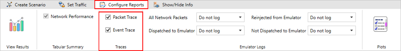
Enable Packet Trace, Event Trace (Optional)
Click the Packet Trace / Event Trace icon in the Configure Reports option and check Enable Packet Trace / Event Trace check box. For detailed help about the packet and event trace, please refer to sections 8.4 and 8.5 in the User Manual.
Enable protocol specific logs and plots
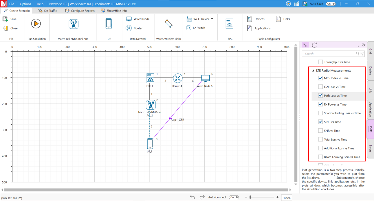
NetSim provides protocol-specific logs for LTE libraries, which users can enable before running a simulation. These can be enabled by clicking on configure reports in top ribbon > clicking on plots > choosing as desired, and running the simulation.
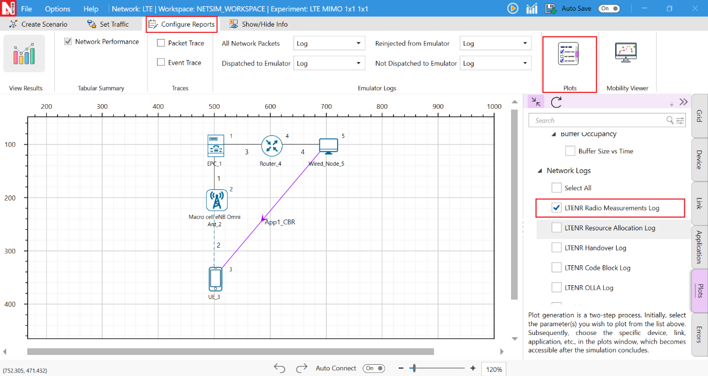
Similarly, users can enable the plots for LTE Radio Measurements.
GUI Configuration of LTE
The LTE parameters can be accessed by right clicking on eNB or UE and selecting Interface (LTE) Properties \(\rightarrow\) Datalink and Physical Layers as shown in the table below.
| Parameter | Type | Range | Description |
|---|---|---|---|
| Scheduling Type | Global | Round Robin | The scheduler serves equal portion to each queue in circular order, handling all processes without priority. |
| Scheduling Type | Global | Proportional Fair | Schedules proportional to the CQI of the UEs. |
| Scheduling Type | Global | Max Throughput | Schedules to maximize the total throughput of the network by giving scheduling priority accordingly. |
| EWMA Learning Rate | Local | to 0.1 | EWMA Averaging Rate (\(\alpha\)) determines how important the
current observation is in the calculation of the EWMA. A lower alpha
discounts older data faster thereby placing greater relevance on your
more recent data. \(\displaystyle EWMA(t)=\left(1-\frac{1}{\alpha}\right)\times EWMA(t-1)\) \(\displaystyle +\left(\frac{1}{\alpha}\right)\times \tau(t)\) \(\displaystyle 0<\frac{1}{\alpha}\leq 1\) |
| Measurement Interval (ms) | Local | to 40960ms | This is the time interval between two UE Measurement reports. |
| RRC MIB Period (ms) | Local | The UE needs to first decode MIB for it to receive other system information. MIB is transmitted on the DL-SCH (logical channel: BCCH) with a periodicity of 80 ms and variable transmission repetition periodicity within 80 ms. MIB packets are visible in the NetSim packet trace post simulation under Control Packet type. | |
| RRC SIB Period (ms) | Local | SIB1 also contains radio resource configuration information that is common for all UEs. SIB1 is transmitted on the DL-SCH (logical channel: BCCH) with a periodicity of 80 ms and variable transmission repetition periodicity within 80 ms. SIB1 is cell-specific. SIB1 packets can be seen in the NetSim packet trace post simulation under Control Packet type. | |
| PDCP Header Compression | Link Global | True / False | Header compression of IP data flows using the ROHC protocol, Compresses all the static and dynamic fields. |
| PDCP Discard Delay Timer | Link Global | /150/300/500/750/1500 | The discard Timer expires for a PDCP SDU, or the successful delivery of a PDCP SDU is confirmed by PDCP status report, the transmitting PDCP entity shall discard the PDCP SDU along with the corresponding PDCP Data PDU. |
| PDCP Out of Order Delivery | Link Global | True / False | Complete PDCP PDUs can be delivered out-of-order from RLC to PDCP. RLC delivers PDCP PDUs to PDCP after the PDU reassembling. |
| PDCP T Reordering Timer | Link Global | –500ms | This timer is used by the receiving side of an AM RLC entity and receiving AM RLC entity in order to detect loss of RLC PDUs at lower layer. |
| RLC T Status Prohibit | Global | –2400ms | This timer is used by the receiving side of an AM RLC entity in order to prohibit transmission of a STATUS PDU. |
| RLC T Reassembly | Link Global | –200ms | This timer is used by the receiving side of an AM RLC entity and receiving UM RLC entity in order to detect loss of RLC PDUs at lower layer. If t-Reassembly is running, t-Reassembly shall not be started additionally, i.e. only one t-Reassembly per RLC entity is running at a given time. |
| RLC T Poll Retransmit | Link Global | –4000ms | This is used by the transmitting side of an AM RLC entity in order to retransmit a poll. |
| RLC Poll Byte | Link Global | 1kB–40mB | This parameter is used by the transmitting side of each AM RLC entity to trigger a poll for every pollByte bytes. |
| RLC Poll PDU | Link Global | p4–p65536 (in multiples of 8) | This parameter is used by the transmitting side of each AM RLC entity to trigger a poll for every pollPDU PDUs. |
| RLC Max Retx Threshold | Link Global | t1, t2, t3, t4, t6, t8, t16, t32 | This parameter is used by the transmitting side of each AM RLC entity to limit the number of retransmissions of an AMD PDU. |
| Handover Interruption time | Link Global | –100ms | The handover process in NetSim is based on event A3 i.e., the target signal strength is offset (3 dB) higher than the source signal strength. Handover interruption time (HIT) is added at the time of handover command is delivered to the UE. During this time there is no data plane traffic flow to the UE from the source/target. |
| Handover Margin | Global | –10dB | The handover Margin is the offset in dB that is used as part of the event A3 handover process in NetSim. Handover is triggered when the target signal strength exceeds the source signal strength by the offset. Range for Handover margin is from 0.0 to 10.0 with 3.0 as default. |
| Time to Trigger | Global | –5120ms | With Time-to-Trigger, the handover is initiated only if the triggering requirement is fulfilled for a time interval specified by Time-to-Trigger (ms). This parameter can decrease the number of unnecessary handovers and effectively avoid Ping-Pong effects. 3GPP defines 16 valid values for time-to-trigger (all in milliseconds): 0, 40, 64, 80, 100, 128, 160, 256, 320, 480, 512, 640, 1024, 1280, 2560, and 5120. Users can enter any value between 0 to 5120 in milliseconds. |
| HARQ Mode | Local | TRUE, FALSE | Hybrid automatic repeat request (hybrid ARQ or HARQ) is a combination of retransmissions and error correction. The HARQ protocol runs in the MAC and PHY layers. In the 5G PHY, a code block group (CBG) is transmitted over the air by the transmitter to the receiver. If the CBG is successfully received the receiver sends back an ACK, else if the CBG is received in error the receiver sends back a NACK (negative ACK). If the transmitter receives an ACK, it sends the next CBG. However, if the transmitter receives a NACK, it retransmits the previously transmitted CBG. Large number packet errors can be observed in packet trace if HARQ is turned OFF. |
| HARQ Retry Limit | Local | –4s | HARQ Retry Limit specifies the number of retransmissions attempts that will be made whenever a Code Block fails due to error. |
| MAX HARQ process count | Local | ,4,6,8 | A HARQ entity is defined for each gNB-UE pair, separately for Uplink and Downlink and for each component carrier. The HARQ entity handles the HARQ processes. Max number of HARQ processes is 8 in 4G. Max number of HARQ processes is 16 in 5G. |
| Max CBG per TB | Local | ,4,6,8 | Each Transport block is split into Code blocks (CBs) and CBs are grouped into Code Block Groups (CBGs). A Code Block group can have up to 2/4/6/8 CBs. |
| Frame Duration (ms) | Fixed | 10ms | Length of the frame. |
| Sub Frame Duration (ms) | Fixed | 1ms | Length of the Sub-frame. |
| Subcarrier Number Per PRB | Fixed | NR defines physical resource block (PRB) where the number of subcarriers per PRB is the same for all numerologies. | |
| eNB Height (m) | Local | – 150 meters | Height of the base station (gNB) in meters. NetSim implements the 3GPP propagation models in which the Indoor gNB (placed within a building) range is 1 to 10 meters, while the Outdoor gNB range is 1 to 150 meters. NetSim only enforces the upper limit of 150m for both indoor and outdoor gNBs. |
| TX Power (dBm) | Local | \(-40\) dBm to 100 dBm | It is the signal intensity of the transmitter. The higher the power radiated by the transmitter’s antenna the greater the reliability of the communications system. |
| TX Antenna Count | Local | /2/4 | The number of transmit antennas. This parameter taken effect during MIMO operation; the number of MIMO layers would be Min(\(N_t\), \(N_r\)), where \(N_t\) is the transmit antenna count at the transmitter and \(N_r\) is the receive antenna count at the receiver. The layer wise gains depends on the fading model chosen and is explained in the 5G NR manual, digital beamforming section. |
| RX Antenna Count | Local | /2/4 | The number of receive antennas. This parameter taken effect during MIMO operation; the number of MIMO layers would be Min(\(N_t\), \(N_r\)), where \(N_t\) is the transmit antenna count at the transmitter and \(N_r\) is the receive antenna count at the receiver. The layer wise gains depends on the fading model chosen and is explained in the 5G NR manual, digital beamforming section. |
| Duplex Mode | Fixed | TDD / FDD | In TDD, the upstream and downstream transmissions occur at different times and share the same channel. In FDD, there are different frequency bands used uplink and downlink. The UL and DL transmission can occur simultaneously. |
| CA Type | Local | Inter band CA, Intra band Contiguous CA, Intra band Non-contiguous CA, Single band | Carrier Aggregation (CA) is used in LTE/5G in order to increase the bandwidth, and thereby increase the bitrate. CA options are intra-band (contiguous and non-contiguous), inter-band and single band. LTE Single Operating Band are referred from 3GPP 36101-h60. |
| CA Configuration | Local | Depends on CA Type | Drop down provides the various bands available for the selected CA type (e.g., n78, n258, n261 etc). |
| CA Count | Fixed | Depends on CA Type | Single or multiple carriers depending on the CA Type chosen. |
| Slot Type | Local | Mixed, Downlink, Uplink | Mixed supports DL and UL traffic. Downlink supports only DL traffic. Uplink supports only UL traffic. |
| DL:UL Ratio | Local | Represents the ratio in which slots are assigned to downlink and uplink transmission. | |
| Frequency Range | Fixed | FR1 | Frequency range for LTE is Frequency Range 1 (FR1) that includes sub-6 GHz frequency bands. |
| Operating Band | Fixed | The LTE operates in different operating bands corresponding to CA configuration respectively. | |
| F Low (MHz) | Fixed | Lowest frequency of the Uplink/Downlink operating band. | |
| F High (MHz) | Fixed | Highest frequency of the Uplink/Downlink operating band. | |
| Numerology | Local | \(\mu = 0\) | It is the numerology value which represents the subcarrier spacing. |
| Channel Bandwidth (MHz) | Local | –20 MHz | The frequency range that constitutes the channel. |
| PRB Count | Local | PRB stands for physical resource block. The PRB count is determined automatically by NetSim as per the other inputs and cannot be edited in the GUI. | |
| Guard Band (KHz) | Local | Guard band is the unused part of the radio spectrum between radio bands, for the purpose of preventing interference. | |
| Subcarrier Spacing | Local | kHz | The LTE radio link is divided into three dimensions: frequency, time and space. The frequency dimension is divided into subcarriers with 15 kHz spacing in normal operation. |
| Bandwidth PRB | Local | KHz | Physical Resource Block Bandwidth is a range of frequencies occupied by the radio communication signal to carry most of PRB energy. |
| Slot per Frame | Local | Slot within a frame depends on the slot configuration. | |
| Slot per Subframe | Local | Slot within a Subframe depends on the slot configuration. | |
| Slot Duration (\(\mu\)s) | Local | Slot duration depends on numerology. The general tendency is that slot duration gets shorter as subcarrier spacing gets wider. | |
| Cyclic Prefix | Local | Normal | Cyclic prefix is used to reduce ISI(Inter Symbol Interference), If you completely turn off the signal during the gap, it would cause issues for an amplifier. To reduce this issue, we copy a part of a signal from the end and paste it into this gap. This copied portion prepended at the beginning is called ‘Cyclic Prefix’. |
| Symbol per Slot | Local | The number of OFDM symbol per slot is 7 in normal cyclic prefix case. | |
| Symbol Duration (ms) | Local | ms | Symbol duration depends on the subcarrier spacing. |
| BWP | Local | Disable | A Bandwidth Part (BWP) is a contiguous set of physical resource blocks (PRBs) on a given carrier. These PRBs are selected from a contiguous subset of the common resource blocks for given numerology (\(\mu\)). This parameter was included in NetSim v13.1, as is reserved for future use. It therefore currently always set as disabled. |
| Overhead (%) per DL slot | Local | –0.99, Default 0.25 | This represents the fraction of symbols in
a slot used for control signaling. The remaining fraction is used for
data transmission. In NetSim calculations are done over aggregated PRBs
per the formula given below: Data PRB available = Total PRB available \(-\) Ceil(Total PRB available \(\times\) Overhead Fraction). In 4G Network the default value is 0.25. |
| Overhead (%) per UL slot | Local | –0.99, Default 0.25 | This represents the fraction of symbols in
a slot used for control signaling. The remaining fraction is used for
data transmission. In NetSim calculations are done over aggregated PRBs
per the formula given below: Data PRB available = Total PRB available \(-\) Ceil(Total PRB available \(\times\) Overhead Fraction). In 4G Network the default value is 0.25. |
| RX Antenna Count | Local | , 2, 4 | The number of receive antennas. |
| TX Antenna Count | Local | , 2, 4, 8, 16, 32, 64, 128 in gNB (1, 2, 4, 8, 16 in UE) | The number of transmit antennas. Power is split equally among the transmit antennas. |
| MCS Table | Local | QAM64LOWSE, QAM64, QAM256 | MCS (Modulation Coding Scheme) is related to Modulation Order. |
| X Overhead | Local | XOH0 | Accounts for overhead from CSI-RS, CORESET, etc. If the xOverhead in PDSCH-ServingCellconfig is not configured (a value from 0), \(N_{oh}^{PRB}\) is set to 0. |
| Transform Precoding | Local | Enable | Transform Precoding is the first step to create DFT-s-OFDM waveform. Transform Precoding is to spread UL data in a special way to reduce PAPR(Peak-to-Average Power Ratio) of the waveform. In terms of mathematics, Transform Precoding is just a form of DFT(Digital Fourier Transform). |
| MCS Table | Local | QAM64LOWSE, QAM64, QAM256 | MCS (Modulation Coding Scheme) is related to Modulation Order. This is based on 3GPP 38.214-Table 5.1.3.1-1, 5.1.3.1-2 and 5.1.3.1-3. Users must set the MCS and CQI tables in the following combination: QAM64: CQI Table 1, QAM 256: CQI Table 2, QAM 64 LOWSE: CQI Table 3. |
| MCS Table | Local | QAM64LOWSE, QAM64, QAM256 | MCS (Modulation Coding Scheme) is related to Modulation Order. This is based on 3GPP 38.214-Table 5.1.3.1-1, 5.1.3.1-2 and 5.1.3.1-3. Users must set the MCS and CQI tables in the following combination: QAM64: CQI Table 1, QAM 256: CQI Table 2, QAM 64 LOWSE: CQI Table 3. |
| Pathloss Model | Local | 3GPP TR38.901-7.4.1, LOG DISTANCE, NONE | None represents an ideal channel with no pathloss. TR 38.901 Standard Table 7.4.2-1 means pathloss will be calculated per the formulas in this standard. |
| Outdoor Scenario | Local | Rural Macro (RMa) | For RMa, we need to specify the Building Height and Street Width. Buildings can be used in the scenario. UEs can be inside/outside buildings but eNBs can only be outside buildings. |
| Outdoor Scenario | Local | Urban Macro (UMa) | Buildings can be used in the scenario. UEs can be inside/outside buildings but eNBs can only be outside buildings. |
| Outdoor Scenario | Local | Urban Micro (UMi) | Buildings can be used in the scenario. UEs can be inside/outside buildings but eNBs can only be outside buildings. |
| Building Height | Local | –50m | It is the height of the building in meters. |
| Street Width | Local | –50m | It is the width of the street in meters. |
| Indoor Scenario | Fixed | Indoor Office | Automatically chosen by NetSim in case the UE is within an indoor building. |
| Indoor Office Type | Local | Mixed-Office, Open-Office | The pathloss will be per the chosen option when the UE is within a building. |
| LOS_NLOS Selection | Fixed | 3GPP TR38.901-Table 7.4.2-1, USER DEFINED | This choice determines how NetSim decides if the eNB-UE communication is Line-of-sight or Non-Line-of-Sight. In case of USER_DEFINED the LOS probability is user defined. Else it is standards defined. |
| LOS Probability | Local | to 1 | If LOS Probability = 1, the LOS mode is set to Line-of-Sight and if the LOS Probability = 0, the LOS mode is set to Non-Line-of-Sight. For a value in between the LOS is determined probabilistically. By default, value is set to 1. |
| Shadow Fading Model | Local | NONE, LOG NORMAL | Select NONE to Disable Shadowing. Select LOG_NORMAL to Enable Shadowing Model, and the Std dev would be per 3GPP TR38.901-Table 7.4.1-1. |
| Fading and Beamforming | Local | No Fading MIMO unit gain, No fading MIMO array gain, Rayleigh with Eigen beamforming, Rician with Eigen beamforming | RAYLEIGH WITH EIGEN BEAMFORMING: When
fading and beamforming is enabled, NetSim uses the rich scattering in
the channel to form spatial channels. The number of spatial channels is
equal to the number of layers (in turn equal to Min(\(N_t,N_r\))). The beamforming gains in the
spatial channel is equal to the eigenvalues of the channel covariance
(Wishart) matrix. When running in SISO (\(N_t=N_r=1\)) this simply simulates Rayleigh
fading. No fading MIMO unit gain: No fading with gain equal to unity (0 dB). No fading MIMO array gain: No fading but gain equals array gain. RICIAN WITH EIGEN BEAMFORMING: In Rician fading, the channel combines a dominant Line-of-Sight (LoS) component with scattered (Rayleigh) components. NetSim forms spatial channels equal to Min(\(N_t,N_r\)) layers, with beamforming gains set by the eigenvalues of the Rician channel covariance matrix. The dominant eigenvalue (strongest layer) is boosted by the LoS path, delivering higher gains than Rayleigh fading, particularly in strong LoS scenarios. For SISO (\(N_t=N_r=1\)), this reduces to Rician fading with a defined K-factor (LoS-to-scattered power ratio). |
| O2I Building Penetration Model | Local | None, Low Loss Model, High Loss Model | The composition of low and high loss is a
simulation parameter that should be determined by the user of the
channel models and is dependent on the buildings and the deployment
scenarios. None to disable O2I Loss. Low-loss model is applicable to RMa. High-loss model is applicable to UMa and UMi. |
| Additional Loss Model | Local | NONE, MATLAB | Additional Loss model can be set to None or MATLAB. If set to MATLAB then MATLAB will be automatically called by NetSim during execution. |
| Path Loss Exponent (n) | Local | to 5 | Path loss exponent indicates the rate at which the path loss increases with distance. The value depends on the specific propagation environment. Set any value between 2 to 5. |
| Shadowing Model | Local | Constant, Log Normal | Constant: A shadowing model is used to
represent the signal attenuation caused by obstructions along the
propagation path. The constant shadowing model is suitable for the
scenarios without mobility where the obstructions along the propagation
paths remain unchanged. Log Normal: The lognormal shadowing model is suitable for a scenario with mobility and obstructions within the propagation environment. In this model, the shadowing value follows a log-normal distribution with a user specified standard deviation. In general, this value should be in the range of 5 to 12 dB depending on the density of obstructions within the propagation environment. |
| Standard Deviation (dB) | Local | to 12 dB | Shadowing is caused mainly by terrain features of the radio propagation environment. The mathematical model for shadowing is a log-normal distribution with standard deviation of 5 to 12 dB. Set any value between 5 to 12 dB. |
| Downlink Interference Model | Global | NO INTERFERENCE, GRADED DISTANCE BASED WYNER MODEL, EXACT GEOMETRIC MODEL | DL interference options are No interference, Graded Distance based Wyner model and Exact geometric models. If no interference is chosen then in the SINR calculations, the values of I is set to zero. Wyner and geometric models compute interference. Wyner is an approximate model used by the research community while the geometric model is exact. Technical details of the two models are provided in the 5G/LTE NR manual. |
| Uplink Interference Model | Global | NO INTERFERENCE, INTERFERNEC OVER THERMAL | NetSim uses Interference-over-thermal (IoT), to model co-channel uplink interference. |
| IoT value (dB) | Global | to 20 | The Uplink IoT (dB) value is used to
compute the SINR, and Interference power based on the following
equations: \(SINR\,(dB) = SNR(dB) - IoT(dB)\) The interference power (dBm units), logged in the radio measurements file will be given as \(I\,(dBm) = 10 \times \log_{10}\left(N \times \left(10^{IoT(dB)}-1\right)\right)\) where \(N\) is thermal noise and is equal to \(k \times T \times B\). |
| MCS Selection Model | Global | IDEAL SHANNON THEOREM BASED RATE, SHANNON RATE WITH ATTENUATION FACTOR | MCS Selection Model determines how
modulation and coding scheme is determined in 5G and LTE. The following Models are supported: Ideal Shannon Theorem-Based Rate: Spectral Efficiency is computed as \(SpectralEfficiency = \log(1+SINR)\) Shannon Rate with Attenuation Factor (\(\alpha\)): Spectral Efficiency is computed as \(SpectralEfficiency = \alpha \times \log(1+SINR)\) Spectral Efficiency - MCS Table is looked up to select the MCS. |
| Attenuation Factor | Global | –1 | Attenuation factor (\(\alpha\)) takes value between 0.5 and 1 with the default value of 0.75. |
| BLER Model | Global | ZERO BLER, BLER ENABLE | Block Error Rate Model (BLER) is used to decide code block and transport block error in 5G and LTE. |
| Outer loop link adaptation | Global | TRUE, FALSE | The Outer Loop Link Adaptation (OLLA) technique, if enabled can improve the channel quality estimation by adjusting the value of SINR by an offset dependent on whether previous transmissions were decoded successfully or not, as captured by Hybrid Automatic Repeat Request (HARQ) feedback. |
| Target BLER | Global | –1 | Target BLER plays an important role in 5G link adaptation. The BLER target is usually around 10% based on specifications. |
| UE Height (meters) | Local | to 22.5 | Height of the UE in meters. |
| TX Power (dBm) | Local | \(-40\) dBm to 50 dBm | It is the signal intensity of the transmitter. The higher the power radiated by the transmitter’s antenna the greater the reliability of the communications system. |
| Tx Antenna Count | Local | /2 | Number of transmit antennas. NetSim uses this parameter in MIMO operations. |
| Rx Antenna Count | Local | /2/4 | Number of receive antennas. NetSim uses this parameter in MIMO operations. |