Featured Examples
NetSim contains some example configuration files to simulate and understand how LTE and LTE-A work.
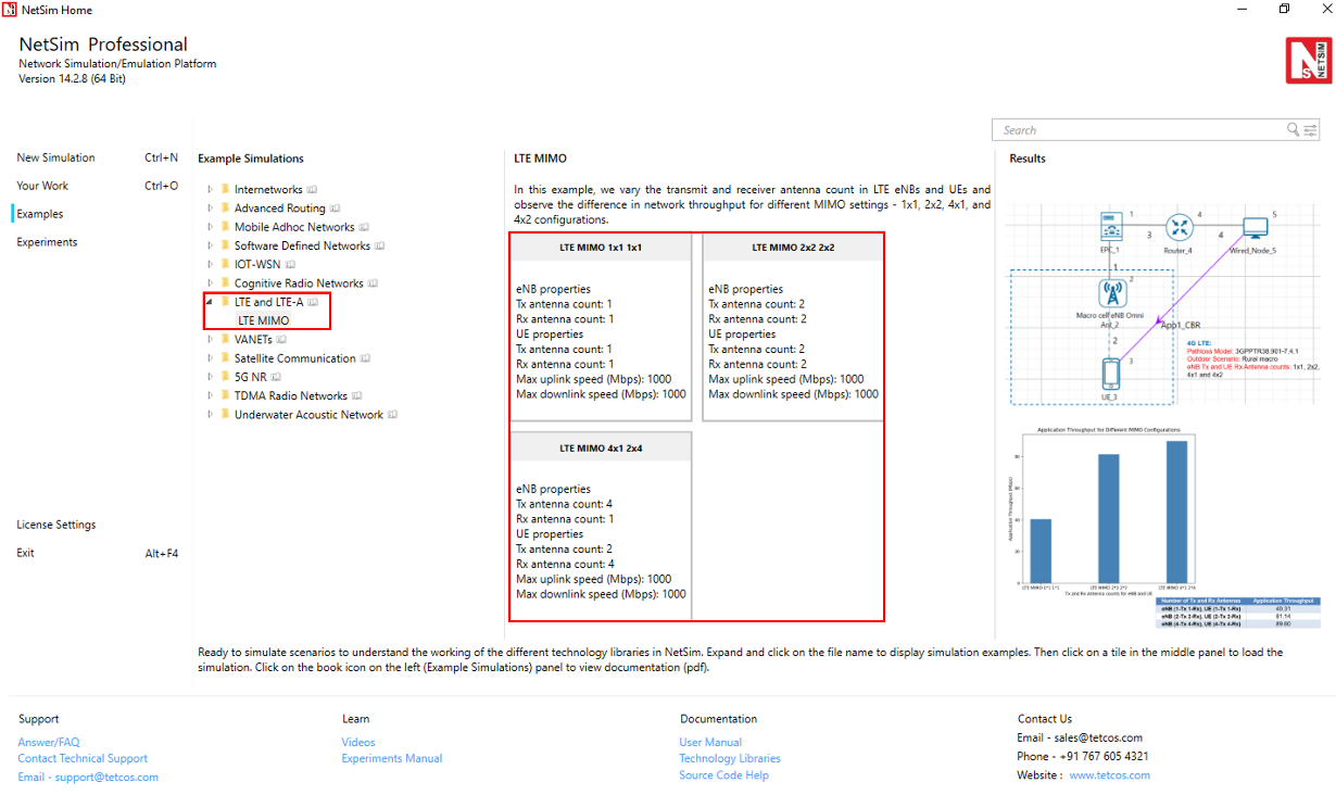
To simulate these examples, click Examples \(>\) LTE and LTE-A in the NetSim Home Screen.
You can change the default values of the parameters in these examples and see how they impact the LTE and LTE-A network.
LTE MIMO
You simulate the example configuration for MIMO in an LTE network’s energy model to understand the impact of SISO and MIMO transmission modes on the throughput of the applications transferred in SISO and MIMO transmission modes.
The LTE network you model from the example configuration file meets the following specifications:
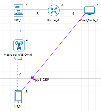
A network with 1 Macro cell eNB, 1 EPC, 1 UE, 1 router, 1 wired node, and 1 unicast application running on the wired node.
Set transport protocol to UDP in Application icon present in the top ribbon/toolbar.
NetSim uses the following defaults for this example:
Each one the unicast applications transmit data at a constant bit-rate from wired Node 5 to the UE.
The simulation runs for 2 seconds.
To simulate the example for SISO and MIMO in an LTE network in NetSim:
Open NetSim and Select Examples \(>\) LTE and LTE-A \(>\) LTE MIMO then click on the tile in the middle panel to load the example as shown in below screenshot.
The following network diagram illustrates what the NetSim UI displays when you open the example configuration file.
NetSim sets all wired link speeds to 1000 Mbps by default. To do so:
Click on the wired link between the eNB and the EPC and expand the right-side property panel. The Link properties pop-up window appears.
NetSim specifies a value of 1000 in the Max Uplink Speed (Mbps) and Max Downlink Speed (Mbps) fields, with the Uplink BER and Downlink BER set to 0.0000001.
Repeat steps (a) to (c) for the wired links between the EPC, router and the wired node.
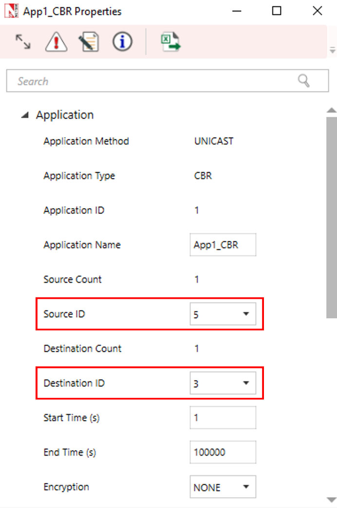
See that by default, NetSim has created unicast applications and specified some default settings. To do so:
Click on the Set Traffic tab and set CBR application with Source ID as 5 and Destination ID as 3 with 90 Mbps Generation Rate (Packet Size: 1460, Inter Arrival Time: 129.78 \(\mu\)s).
Set the start time to 1s.
Go to eNB properties \(\rightarrow\) Interface 2 (LTE) \(\rightarrow\) Physical layer.
| Properties | Value |
|---|---|
| Component Carrier 1 | |
| DL:UL Ratio | 4:1 |
| Bandwidth | 5 MHz |
| Component Carrier 2 | |
| DL:UL Ratio | 4:1 |
| Bandwidth | 10 MHz |
| Antenna | |
| TX Antenna Count / RX Antenna Count | 1 For Both eNB and UE / 1 For Both eNB and UE |
| Channel Model | |
| Pathloss Model | 3GPP TR38.901-7.4.1 |
| Outdoor Scenario | Rural macro |
| LOS NLOS Selection | User defined |
| LOS Probability | 1 |
| Shadow Fading Model | None |
| Fast Fading Model | No fading |
| MIMO Beamforming Model | Array Gain |
Simulate the LTE MIMO. To do so:
Click the Run icon located on the toolbar. The Run Simulation pop-up window appears.
Retain the default settings in the Simulation Configuration tab (Simulation time = 2 Sec).
Click Run.
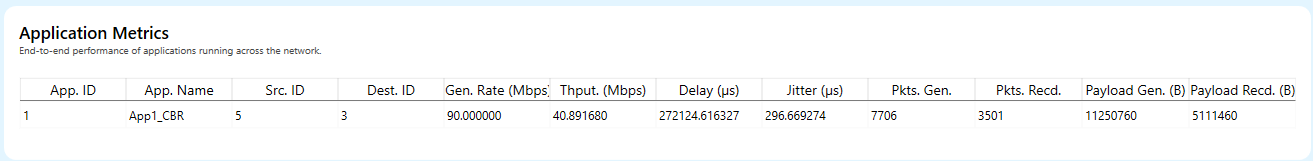
Results and Discussion
After NetSim simulates the LTE MIMO, NetSim displays the Simulation results window.
To interpret the results, check the values of the throughputs in the Application Metrics Table window. You will see the following throughput values for Application 1 is 40.89 Mbps.
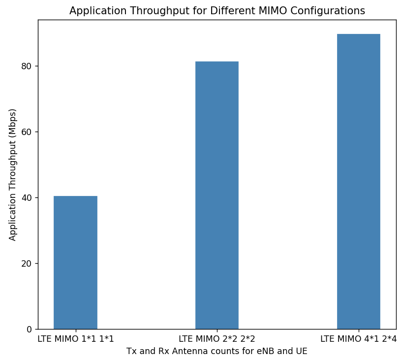
The Application Throughput (Mbps) column in the table lists the throughput values for different Tx Antennas Count and Rx Antennas Count configurations.
| Number of Tx and Rx Antennas Count for eNB and UE | Application Throughput (Mbps) |
|---|---|
| eNB (1-Tx 1-Rx), UE (1-Tx 1-Rx) | 41.41 |
| eNB (2-Tx 2-Rx), UE (2-Tx 2-Rx) | 82.79 |
| eNB (4-Tx 1-Rx), UE (2-Tx 4-Rx) | 89.60 |
Plot
Note: The throughput values may vary depending on the position of the nodes when using different Tx Antennas Count and Rx Antennas Count configurations.