Simulation GUI
Open NetSim and click New Simulation -> Internetworks as shown Figure-1.

Figure-1: NetSim Home Screen
Create Scenario
Internetworks come with a palette of various devices like L2 Switch, L3 Switch, Router, Wired Node, Wireless Node, and AP (Access Point).
Devices specific to NetSim Internetworks Library
Wired node: A Wired node can be an end-node or for a server. It is a 5-layer device that can be connected to a switch and router. It supports only 1 Ethernet interface and has its own IP and MAC Addresses.
Wireless Nodes: A Wireless node can be an end-node or a server. It is a 5-layer wireless device that can be connected to an Access Point. It supports only 1 Wireless interface and has its own IP and MAC Addresses.
L2 Switch: Switch is a layer-2 device that uses the devices MAC address to make forwarding decisions. It does not have an IP address.
L3 Switch: A Layer 3 switch operates at both the data link layer and the network layer . It combines the functionality of a traditional switch and a router.
Router: Router is a layer-3 device and supports a maximum of 24 interfaces each of which has its own IP address.
Access Point: Access Point (AP) is a layer-2 wireless device working per 802.11 Wi-Fi protocol. It can be connected to wireless nodes via wireless links and to a router or a switch via a wired link.

Figure-2: Internetworks Device Palette in GUI
Click and drop into environment
Add a Wired Node or Wireless Node: In the toolbar, click the Node > Wired Node icon (or) Node >Wireless Node icon, and place the device in the grid.
Note: Wireless nodes can be effortlessly connected using the auto-connect feature, ensuring that users first drop the access point before adding the wireless node.
Add a Router: In the toolbar, click on the Router icon and place the Router in the grid.
Add an L2 Switch or L3 Switch: In the toolbar, click on Switch > L2 Switch icon (or) Switch > L3 Switch icon and place the device in the grid.
Add an Access Point: In the toolbar, click on the Access Point icon and place the access point in the grid.
Connect the devices by using Wired/Wireless Links present in the top ribbon/toolbar. Click on the first device and then click on the second device. A link will be formed between the two devices.
Note: Wireless devices get auto connected, whereas wired devices need physical connection.
Configure an application by following these steps:
Click on the Set Traffic tab in the top ribbon/toolbar.
Select any application from the list and configure the traffic between source and destination.
Specify other application parameters per your model.
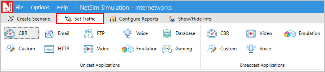
Figure-3: Top Ribbon/Toolbar
Repeat (ii) to generate multiple applications. Detailed information on application properties is available in section 6 of NetSim User Manual.
Clicking on any device (Router, Access Point, L2 Switch, Wireless Node, Wired Node, etc.) will open a right-side property panel, allowing users to set the parameters.

Figure-4: Device Properties
In the Wireless Interface, Physical Layer and Data Link Layer parameters are local, but in the Physical Layer, the Standard parameter is global. To set the same parameter value across all devices, ensure that you update the parameter values manually in all other devices (Access Point or Wireless Node) as the parameter change does not propagate automatically due to its local nature.
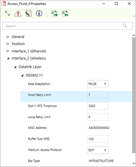
Figure-5: MAC properties of Access Point

Figure-6: PHY Layer properties of Access Point
Link Properties
Clicking on the link will open a right-side property panel where users can set the link properties. Note that when simulating Internetworks if the link propagation delay is set too high then the applications may not see any throughput since it would take too long for OSPF to converge, and furthermore, TCP may also timeout (since max RTO is 3s).

Figure-7: Link Properties
Enable Packet Trace, Event Trace & Plots (Optional)
Click the Packet Trace / Event Trace icon in the Configure Reports Option and check the Packet Trace / Event Trace check box. For detailed help about the packet and event trace, please refer to sections 8.4 and 8.5 in the User Manual

Figure-8: Packet Trace, Event Trace & Plots options on top ribbon.
Enable protocol specific logs and plots
NetSim provides protocol-specific logs for Internetworks libraries, which users can enable before running a simulation. These can be enabled by navigate to the Configure Reports section in the top ribbon, select Plots, and choose the desired options, and running the simulation

Figure-9: Enabling the Network logs in Internetworks
Similarly, users can enable the plots for Wi-Fi radio measurements.

Figure-10: Enabling the Wi-Fi Radio measurements plots in Internetworks
Run Simulation
Click on the Run Simulation icon on the top ribbon/toolbar. For detailed help, please refer to section 3.5 of the User Manual.
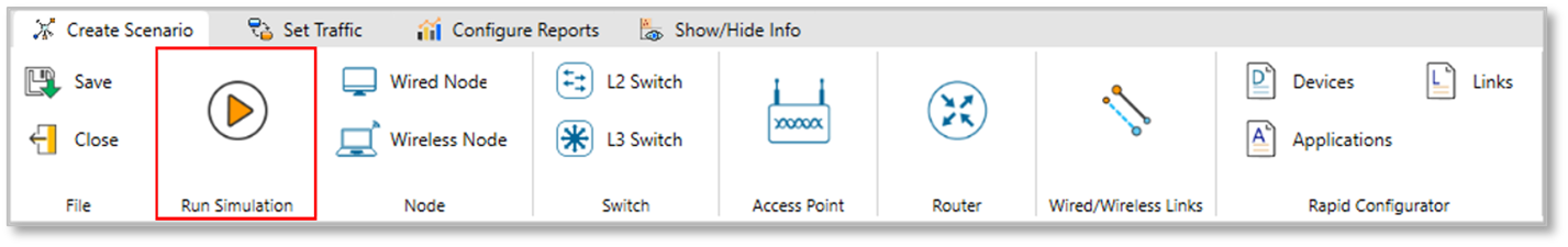
Figure-11: Run Simulation on top ribbon
Set the Simulation Time and click on the Run button.

Figure-12: Run Simulation window.