Model Features
Implementation of the 802.11p in NetSim
The Ad hoc Wi-fi MAC allows for STA transmissions of data frames outside-the-context-of-a-BSS (OCB). Establishing a secure BSS necessitates announcement, scanning, synchronization, and association and the time required is extremely undesirable in vehicular environments. NetSim therefore allows for direct and instantaneous link setups with no establishment of a BSS. There is no authentication nor association.
Supports a channel bandwidth of 5MHz, 10 MHz, 20MHz in the 5.9 GHz band
Supported PHY rates are as follows:
1.5, 2.25, 3, 4.5, 6, 9, 12 and 13.5 Mbps for 5MHz
3, 4.5, 6, 9, 12, 18, 24 and 27 Mbps for 10MHz.
6, 9, 12, 18, 24, 36, 48 and 54 Mbps for 20MHz.
The PHY rates for IEEE 802.11p in NetSim are determined from the MCS tables of IEEE 802.11-OFDM (provided below). The receiver measures the received power and is assumed to transmit this information to the transmitter instantaneously and out of band. The transmitter compares the received power to the receiver sensitivity and selects the MCS where the received power meets or exceeds the sensitivity.
Transmission type is OFDM
with slot time equal to 9 \(\mu s\) and SIFS equal to 16 \(\mu s\) for 20 MHz
with slot time equal to 13 \(\mu s\) and SIFS equal to 32 \(\mu s\) for 10 MHz
with slot time equal to 21 \(\mu s\) and SIFS equal to 64 \(\mu s\) for 5 MHz
Uses a Medium Access Control (MAC) protocol based on the Carrier Sense Multiple Access Collision Avoidance (CSMA/CA) protocol, which is explained below.
When a node wants to send a message, the channel must be idle for a duration of SIFS. If the channel is idle, it starts transmission.
When a node finds the channel busy, it chooses a random backoff time from the interval \([0, CW]\) and transmits only when the backoff timer has elapsed. The variable CW represents the size of the Contention Window.
When the SCH is used and a node does not receive an acknowledgement for a message, it concludes that the message has collided and is lost, so the value of CW is doubled, and it will retry transmission.
In the CCH however, beacons are broadcast in the channel and no acknowledgments are sent. Therefore, the value of CW is never doubled in the CCH.
Introduction of IEEE 802.11bd
IEEE 802.11bd is a vehicular communication standard for Intelligent Transportation Systems (ITS). It is defined as an amendment to IEEE 802.11, operating in the 5.9 GHz band. It supports coexistence with IEEE 802.11p (non-NGV) stations and introduces enhancements to the PHY layer for next generation V2X communication.
NetSim’s VANETs module supports IEEE 802.11bd. The following enhancements are defined in IEEE 802.11bd over IEEE 802.11p:
Spatial stream support: up to 2 transmitting and 2 receiving antennas, supporting spatial diversity.
Frame Aggregation: multiple MPDUs combined into a single PHY transmission, improving channel utilization.
Guard Interval fixed at 1600 ns, as defined in IEEE 802.11bd (Table 32-6).
Bandwidth support for both 10 MHz and 20 MHz channels.
Extended MCS range: NGV-MCS 0–8 (up to 256-QAM), with MCS 9 not valid at 10 MHz.
All other PHY and MAC properties follow the IEEE 802.11bd specification.
Implementation of IEEE 802.11bd in NetSim
The IEEE 802.11bd implementation in NetSim includes vehicular-specific extensions to the standard PHY and MAC. Key aspects are described below.
PHY Layer
Operates in the 5.9 GHz band with 10 MHz and 20 MHz channel bandwidths.
Transmission type: BD.
Slot time (aSlotTime): 13 \(\mu\)s (Table 32-20, IEEE 802.11bd-2022).
SIFS (aSIFSTime): 32 \(\mu\)s (Table 32-20, IEEE 802.11bd-2022).
Guard Interval (\(T_{GI}\)): 1600 ns = \(T_{DFT}/4\), where \(T_{DFT}\) = 6.4 \(\mu\)s (Table 32-6, IEEE 802.11bd-2022).
Up to 2 transmitting and 2 receiving antennas (NSS up to 2).
Frame Aggregation: 1 to 32 frames per PHY transmission.
PHY data rates are derived from the NGV-MCS tables defined in IEEE 802.11bd-2022. The receiver selects the MCS at which received power meets or exceeds the receiver sensitivity threshold (Table 32-16, IEEE 802.11bd-2022).
NGV-MCS Table — 10 MHz, NSS = 1
Source: struPhyParameters_10MHz_1NSS, IEEE 802.11bd-2022 Tables 32-21 and 32-16.
NGV-MCS Table — 10 MHz, NSS = 2
Source: struPhyParameters_10MHz_2NSS, IEEE 802.11bd-2022 Tables 32-22 and 32-16.
NGV-MCS Table — 20 MHz, NSS = 1
Source: struPhyParameters_20MHz_1NSS, IEEE 802.11bd-2022 Tables 32-23 and 32-16.
NGV-MCS Table — 20 MHz, NSS = 2
Source: struPhyParameters_20MHz_2NSS, IEEE 802.11bd-2022 Tables 32-24 and 32-16.
GUI Configuration Parameters
The following tables list the configurable parameters for IEEE 802.11bd Vehicles and RSUs in NetSim, organized by layer.
Physical Layer Parameters
| Parameter | Scope | Range | Description |
|---|---|---|---|
| Standard | Cell | IEEE 802.11bd | IEEE 802.11bd is a vehicular communication standard for Intelligent Transportation Systems (ITS). It operates in the 5.9 GHz band and is backward-compatible with IEEE 802.11p. Enhancements include multi-antenna support, frame aggregation, and extended SCH channel range. |
| Transmit Power | Local | 0–1000 mW | Transmitted signal power per antenna. The transmit power is not split among antennas; the configured value is applied independently to each antenna in a multi-antenna transmitter. Unit: mW. Default: 1000 mW. |
| No. of Frames to Aggregate | Local | 1–32 | Number of MAC Protocol Data Units (MPDUs) combined into a single PHY-layer transmission. A value of 1 disables aggregation. Default: 1. |
| Frequency Band | Fixed | 5.9 GHz | IEEE 802.11bd operates in the 5.9 GHz band, as specified by DSRC/WAVE standards. This parameter is not configurable. |
| Bandwidth | Cell | 10 MHz, 20 MHz | Channel bandwidth. Determines available data rates and spectral occupancy. Default: 10 MHz. |
| SCH Channel | Local | 172_5860 – 184_5920 | Service Channel (SCH) used for non-safety data applications. The SCH channel plan is defined by IEEE 1609.4 and is the same as IEEE 802.11p. IEEE 802.11bd does not define a new channel plan. |
| CCH Channel | Fixed | CCH 178 (5890 MHz) | Control Channel (CCH) used for safety management messages, including Basic Safety Messages (BSM) and WAVE Service Advertisements (WSA). Fixed at 5890 MHz (Channel 178) per IEEE 1609.4. Not configurable. |
| Guard Interval | Fixed | 1600 ns | Guard interval between OFDM symbols. IEEE 802.11bd defines \(T_{GI}\) = 1.6 \(\mu\)s (= \(T_{DFT}\)/4), where \(T_{DFT}\) = 6.4 \(\mu\)s. Protects against inter-symbol interference from multipath propagation. Not configurable. |
| Connection Medium | Fixed | Wireless | IEEE 802.11bd nodes communicate over the wireless medium in OCB (Outside the Context of a BSS) mode, without BSS establishment, authentication, or association. |
| Error Model | Local | SINR-BER-By-Table, SINR-BER-By-Formula | Specifies the method used to compute Bit
Error Rate (BER) during simulation. SINR-BER-By-Table: BER is determined from pre-computed lookup tables mapping SINR to BER per MCS. SINR-BER-By-Formula: BER is computed from mathematical expressions based on SINR and MCS. |
Antenna Parameters
| Parameter | Scope | Range | Description |
|---|---|---|---|
| Antenna Height | Local | 0–100 m | Used in path loss calculations for the following models: Cost231 Hata Urban, Cost231 Hata SubUrban, Hata Urban, Hata SubUrban, and Two Ray. Has no effect when using other path loss models. Default: 0.0 m. |
| Antenna Type | Fixed | Omnidirectional | IEEE 802.11bd uses an omnidirectional antenna, which radiates and receives signals uniformly in the horizontal plane. |
| Antenna Gain | Local | 0–1000 dB | Measure of the antenna’s ability to direct radio frequency energy relative to an isotropic radiator. Expressed in dBi. Default: 0 dB. |
| Transmitting Antennas | Local | 1 or 2 | Number of transmitting antennas. IEEE 802.11bd supports up to 2, enabling spatial multiplexing or transmit diversity. IEEE 802.11p supports only 1. |
| Receiving Antennas | Local | 1 or 2 | Number of receiving antennas. IEEE 802.11bd supports up to 2, enabling receive diversity and MIMO reception. |
Power Parameters
| Parameter | Scope | Range | Description |
|---|---|---|---|
| Power Source | Local | Main Line or Battery | Power source for the node. VANET nodes typically operate on battery. Default is Main Line (AC supply). Configurable with adjustable current and voltage properties. |
| Energy Harvesting | Local | On or Off | When enabled, the node periodically replenishes battery energy based on the configured recharging current and voltage. NetSim uses an abstract harvesting model. |
| Initial Energy | Local | 0.001–1000 mAh | Battery charge at the start of the simulation. |
| Transmitting Current | Local | 0–20 mA | Current drawn when the node is transmitting. Energy consumed scales with the number of packets sent. |
| Idle Mode Current | Local | 0–20 mA | Current drawn when the node is idle (listening to the medium, not transmitting or receiving). |
| Receiving Current | Local | 0–20 mA | Current drawn when the node is receiving data. |
| Recharging Current | Local | 0–20 mA | Current supplied to the battery during energy harvesting. |
| Voltage | Local | 0–10 V | Operating voltage of the node’s power supply. |
Frame Aggregation
Frame aggregation combines multiple MPDUs into a single PHY-layer transmission, improving channel utilization. The parameter is described in the table below.
| Parameter | Scope | Range | Description |
|---|---|---|---|
| No. of Frames to Aggregate | Local | 1–32 | Number of MPDUs combined into a single PHY-layer transmission. A value of 1 means no aggregation. Higher values improve throughput under good channel conditions. Default: 1. |
MAC Layer
The MAC layer defined is same for both 802.11p and 802.11bd based on the standard IEEE 1609 protocol.
Medium access uses CSMA/CA.
DSRC channel switching between CCH and SCH is supported. CCH time, SCH time, and Guard Interval are user-configurable.
BSM (Basic Safety Message) packets are transmitted on the CCH using WSMP over IEEE 1609.
Non-safety application traffic (CBR, FTP, Voice, Video, etc.) is transmitted on the SCH.
Frame aggregation is supported on the SCH.
DSRC Channels: CCH and SCH
Vehicles (OBUs) and RSUs can operate in (switch between) multiple channels i.e., in the SCH and CCH as explained below.
Control channel (CCH): A radio channel, intended for the exchange of management information. In NetSim when a BSM (safety) application is configured, it is transmitted on the CCH.
Service channel (SCH): These are radio channels used for non-safety application. In NetSim, when non safety application such as CBR, Voice, Video, FTP etc., are configured, they are transmitted on the SCH.
Guard interval: A time interval at the start of each control channel (CCH) interval and service channel (SCH) interval during which devices cannot transmit.
Each synchronization interval SI is split as follows:

All devices (Vehicles and RSUs) switch between SCH and CCH and the alternation is based on the time divisions. NetSim allows the user to configure values of CCH interval, SCH interval and Guard interval. NetSim supports 6 service channels (SCH): 172 (5860 MHz), 174 (5870 MHz), 176 (5880 MHz), 180 (5900 MHz), 182 (5910 MHz) and 184 (5920 MHz), and 1 control channel (CCH): 178 (5890 MHz). The default channels used in NetSim are SCH 171 (5.855 GHz) and CCH 178 (5.890 GHz).
BSM Application
DSRC protocol runs with BSM (Basic Safety Message) applications. BSM is a broadcast packet transmitted at a regular interval.
The BSM Application class sends and receives the IEEE 1609 WAVE (Wireless Access in Vehicular Environments) Basic Safety Messages (BSMs). The BSM is a 20-byte packet that is generally broadcast from every vehicle at a nominal rate of 10 Hz. In NetSim this can be configured as a broadcast or as a unicast application. Note that a broadcast application can only be transmitted over a single hop. NetSim does not transmit broadcast applications over multiple hops.
This application does not follow the IP stack. It runs WSMP protocol over IEEE 1609. There is no routing; static routes cannot be set, and packets are sent directly to the destination.
Differences from IEEE 802.11p
IEEE 802.11bd is backward-compatible with IEEE 802.11p. The table below lists the key differences between the two standards as implemented in NetSim.
| Feature | IEEE 802.11p | IEEE 802.11bd |
|---|---|---|
| MAC/PHY Base | IEEE 802.11p | IEEE 802.11bd |
| Guard Interval (\(T_{GI}\)) | 800 ns | 1600 ns (fixed) |
| Slot Time | 13 \(\mu\)s | 13 \(\mu\)s |
| SIFS | 32 \(\mu\)s | 32 \(\mu\)s |
| Transmitting Antennas | 1 | 1 or 2 |
| Receiving Antennas | 1 | 1 or 2 |
| Frame Aggregation | Not supported | 1 to 32 frames |
| MCS Range | MCS 0–7 (up to 64-QAM) | NGV-MCS 0–8 (up to 256-QAM); MCS 9: valid at 20 MHz only |
| Peak Data Rate (10 MHz, 1 NSS) | 27 Mbps | 39 Mbps (NGV-MCS 8) |
| Peak Data Rate (20 MHz, 2 NSS) | 54 Mbps | 180 Mbps (NGV-MCS 9) |
| SCH Channels | channels (172–184) | channels (172–184) (same as 802.11p, per IEEE 1609.4) |
| CCH Channel | CCH 178 (5890 MHz) | CCH 178 (5890 MHz) |
| Bandwidth | 5 MHz, 10 MHz, 20 MHz | 10 MHz, 20 MHz |
| Frequency | 5.9 GHz | 5.9 GHz |
| DSRC/WAVE Protocol | Supported | Supported |
| BSM Application | Supported | Supported |
| SUMO Interfacing | Supported | Supported |
NetSim – SUMO interfacing
NetSim’s VANET module allows users to interface with SUMO which is an open-source road traffic simulation package designed to handle vehicular & road networks. The road traffic simulation is done by SUMO while NetSim does the network simulation along with RF propagation modelling in the physical layer. While SUMO Simulates the road traffic conditions and movements, NetSim Simulates the communication occurring between the Vehicles.
NetSim and SUMO are interfaced using ‘pipes’. A pipe is a section of shared memory that processes use for communication. The SUMO process writes information to pipe, then NetSim process reads the information from pipe. On running the Simulation, SUMO determines the positions of vehicles with respect to time as per the road conditions. NetSim reads the coordinates of vehicles from SUMO (through pipes) in runtime and uses it as input for vehicle mobility.
Users will notice an inversion along X axis in the NetSim GUI, since origin (0, 0) in SUMO is at the left bottom, while origin is at the left top in NetSim.
VANET operates in a wireless environment and hence RF channel loss occurs. The amount of loss can be configured by users. To modify the Wireless channel characteristics users can right click on the ad hoc/wireless link and modify the channel characteristics as per the requirement.
Source code related to interfacing of SUMO and NetSim is available in Sumo_interface.c file inside the mobility folder/project.
How to create a VANET using SUMO and simulate with NetSim
A SUMO network can be created either manually or using SUMO NetEdit.
Using SUMO NetEdit utility and randomtrips.py to configure road traffic models
Netedit is a road network editor for the road traffic simulation in SUMO. This utility enables users to efficiently design road networks and generate the corresponding network XML file, which is an essential component of the SUMO configuration.
Steps to create a simple SUMO network using netedit utility:
Step 1: Open netedit from
<SUMO_INSTALL_DIRECTORY>/bin(C:\Program Files (x86)\Eclipse\Sumo\bin) and select File \(\rightarrow\) New Network
Refer SUMO Documentation: “https://sumo.dlr.de/docs/Netedit/index.html” for more details on modes of operation.

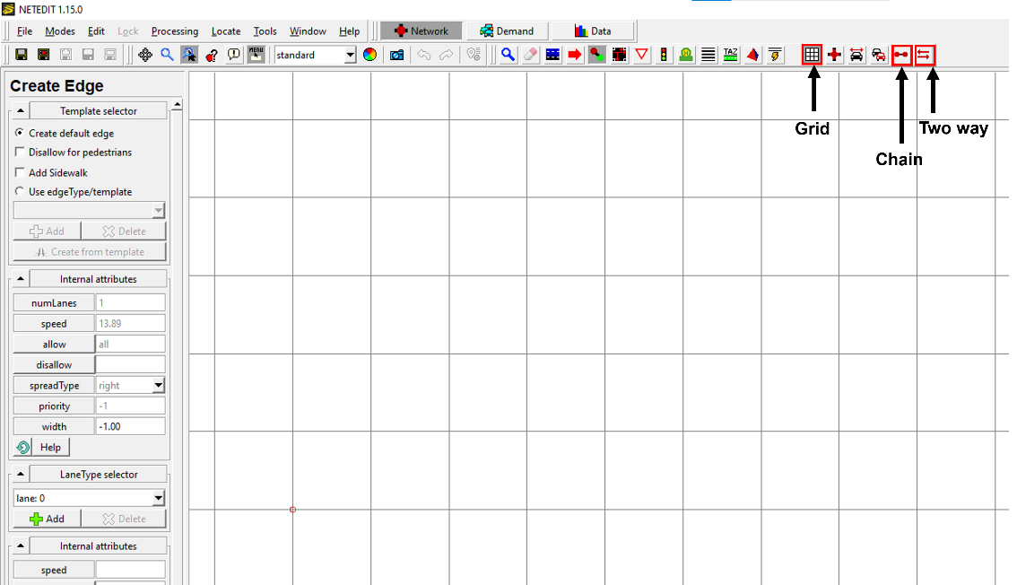
Step 2: Select Creating junction and edges option as shown below or click on character “e” in the keyboard.

Step 3: Enable the check boxes “chain”, “two-way” and “Grid” which are present in the right-side corner.
Step 4: Adjust the design area to ensure that the road network lies in the Positive XY quadrant. This will help in avoiding complexities when opening the network scenario in NetSim.
Step 5: Click on grid area to create edges, clicking again will create a new edge which will automatically get connected to the previous edge as shown below.

Step 6: Select “(t) Traffic Lights”. Select the junctions and click on Create TLS button on the left to add Traffic Signal to it.

Step 7: Select “(c) Connect” icon. Select the lanes and ensure connectivity between them.

Step 8: Create a new folder and save the network file (*.net.xml) over there, say with a name network.net.xml

Step 9: Open command prompt with the current working directory as the folder where you have saved the network file in the previous step.
Step 10: Using randomtrips.py utility present in
<SUMO_INSTALL_DIRECTORY>/toolsdirectory create trips file with the command.
COMMAND SYNTAX:
>"C:\Program Files (x86)\Eclipse\Sumo\tools\randomTrips.py"
   -n "*.net.xml" -e <NO_OF_TRIPS> --route-file "trips.xml"
Example Command:
>"C:\Program Files (x86)\Eclipse\Sumo\tools\randomTrips.py"
   -n "network.net.xml" -e 5 --route-file "trips.xml"
This will create a trips file in your folder along with associated files.
Step 11: Create a “file-settings.xml” file in your folder which contains the network and route file for improving the visualization of vehicles and their movements in a graphical user interface (GUI).
Following is a “file-settings.xml” file:
<viewsettings>
  <scheme name="NetSim_VANET">
    <vehicles vehicleQuality="2" vehicle_exaggeration="4.00">
    </vehicles>
  </scheme>
  <delay value="500"/>
</viewsettings>
Step 12: Create a SUMO configuration file (*.sumo.cfg) which points to the network and trips file, in your folder which contains the network and route file.
Refer: http://sumo.dlr.de/wiki/Tutorials/Hello_Sumo
Include parameter (To Run in NetSim):
"<step-length value="0.4"/>"
Following is a sample SUMO Configuration:
<configuration>
    <input>
        <net-file value="network.net.xml"/>
        <route-files value="trips.xml"/>
        <gui-settings-file value="file-settings.xml"/>
    </input>
    <time>
        <begin value="0"/>
        <end value="100"/>
        <step-length value="0.4"/>
    </time>
</configuration>
NOTE: Save above content as Configuration.sumo.cfg
You can copy the above contents to create a SUMO configuration file in your folder.
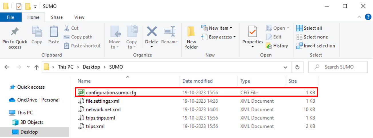
Step 12: Open Configuration.sumo.cfg by double clicking or open SUMO using sumo-gui.exe present in
<SUMO INSTALL DIRECTORY>/bin. Open scenario in SUMO using Open \(\rightarrow\) Simulation and verify whether the network loads and simulation happens as per the configuration done.

Step 13: Open the SUMO scenario via NetSim VANET by selecting VANET under the New Simulation in the NetSim Home Screen. Browse and locate the SUMO Configuration file present in your directory to load the road traffic network in NetSim GUI. The road network created in SUMO will be automatically replicated in NetSim GUI environment.


Step 14: Configure traffic between vehicles using the Application icon, enable trace files and plots.
Step 15: Click on Run Simulation button. The Simulation Time is equal to the end time specified in sumo configuration (sumo.cfg) file and Simulation Time option is Non editable.
Creating your own network in SUMO manually
Step 1: Create a node file using any code editor (like notepad, notepad++ etc.) and the file extension will be .nod.xml. It represents the junctions in the road. Each of these attributes has a certain meaning and value range: node id means unique name of each junction, x-y is the positions of node and type can be “priority”, “traffic_light”, “rail_crossing”, “rail_signal” etc. (Refer: https://sumo.dlr.de/wiki/Networks/PlainXML#Node_Descriptions).

Step 2: Create an edge file that describes how the junctions or nodes are connected to each other. The extension of this file is .edg.xml. Each edge is unidirectional and starts at the “from”-node and ends at the “to”-node. For each edge, some further attributes should be supplied, being the number of lanes the edge has (numLanes), the maximum speed allowed on the edge speed. Furthermore, the priority may be defined optionally. (Refer: https://sumo.dlr.de/wiki/Networks/PlainXML#Edge_Descriptions).

Step 3: Open Command Prompt and change the directory to the binary folder of sumo using cd command.
"cd C:\Program Files (x86)\Eclipse\Sumo\bin"

Step 4: Generate Network file by using NETCONVERT command. Make a folder named like VANET_Example and place the .nod.xml and .edg.xml files i.e. NODES.nod.xml and EDGE.edg.xml respectively.
netconvert --n "<path>\<filename>.nod.xml"
           --e "<path>\<filename>.edg.xml"
           --o "<path>\<filename>.net.xml"
Step 5: Create a .rou.xml file that describes the direction of the vehicle’s movement.

Step 6: Create a sumo configuration file using any code editor (like notepad, notepad++ etc.) and the extension is .sumo.cfg. Place the file inside the same folder where the network file (i.e. NETWORK.net.xml) and route file (i.e. VEHICLES.rou.xml) are present.

Step 7: Now open “New Simulation \(\rightarrow\) VANET”. Choose the Configuration.sumo.cfg from the specified folder and run simulation using NetSim.
How to include Roadside Units (RSUs) in a VANET network
Upon importing a sumo network configuration into NetSim, roads and vehicles are automatically added in NetSim as per the configuration done in SUMO.

Roadside Units can be optionally included in the network by manually clicking and dropping the RSU icon from the ribbon.

RSUs should be connected using ad hoc links manually.

Traffic can be configured between RSUs and vehicles via Application configuration.
Radio measurement log file and plots
NetSim IEEE 802.11 Radio Measurements log file records pathloss, shadowing loss, fading loss, received power, transmitted power, SNR, and BER. This log can be enabled by clicking on configure reports in top ribbon > Plots > Select IEEE 802.11 Radio Measurements log under Network Logs as shown below.

The IEEE802.11 Radio Measurements log.csv file will contain the following information:
Time in Milliseconds
Transmitter Name
Receiver Name
Distance between the Transmitter and the Receiver in meters
Packet ID
Packet Type
Control Packet Type
Transmitter Power in dBm
Pathloss in dB
Shadowing Loss in dB
Fading Loss in dB
Total Loss in dB
Transmitter Antenna Gain in dB
Receiver Antenna Gain in dB
Received Power in dBm
Interference in dBm
SNR in dB
SINR in dB
NSS (Number of Spatial Streams)
BER
MCS Index
The log file can be accessed from the Simulations Results Window under the logs as shown below.


Enabling the plots is explained in the section 2.5. Here is the plot showing the transmit energy vs. time for a DSR scenario with five vehicles.
