Simulation GUI
Create Scenario
Open NetSim and click New Simulation \(>\) Underwater Acoustic Networks as shown in Figure 2-1.

Devices specific to NetSim UWAN Library

Placement of devices on the grid environment
Add an Underwater Device - Click on the Underwater Device icon on the toolbar and place the device in the grid.
Enable Packet Trace, Event Trace (Optional)
Check Packet Trace / Event Trace option from the Configure Reports tab. To get detailed help, please refer to sections 8.4 and 8.5 in User Manual.

Enable protocol specific logs and plots
NetSim provides protocol-specific logs for UWAN libraries, which users can enable before running a simulation. These can be enabled by clicking on configure reports in top ribbon \(>\) clicking on plots \(>\) choosing as desired and running the simulation.
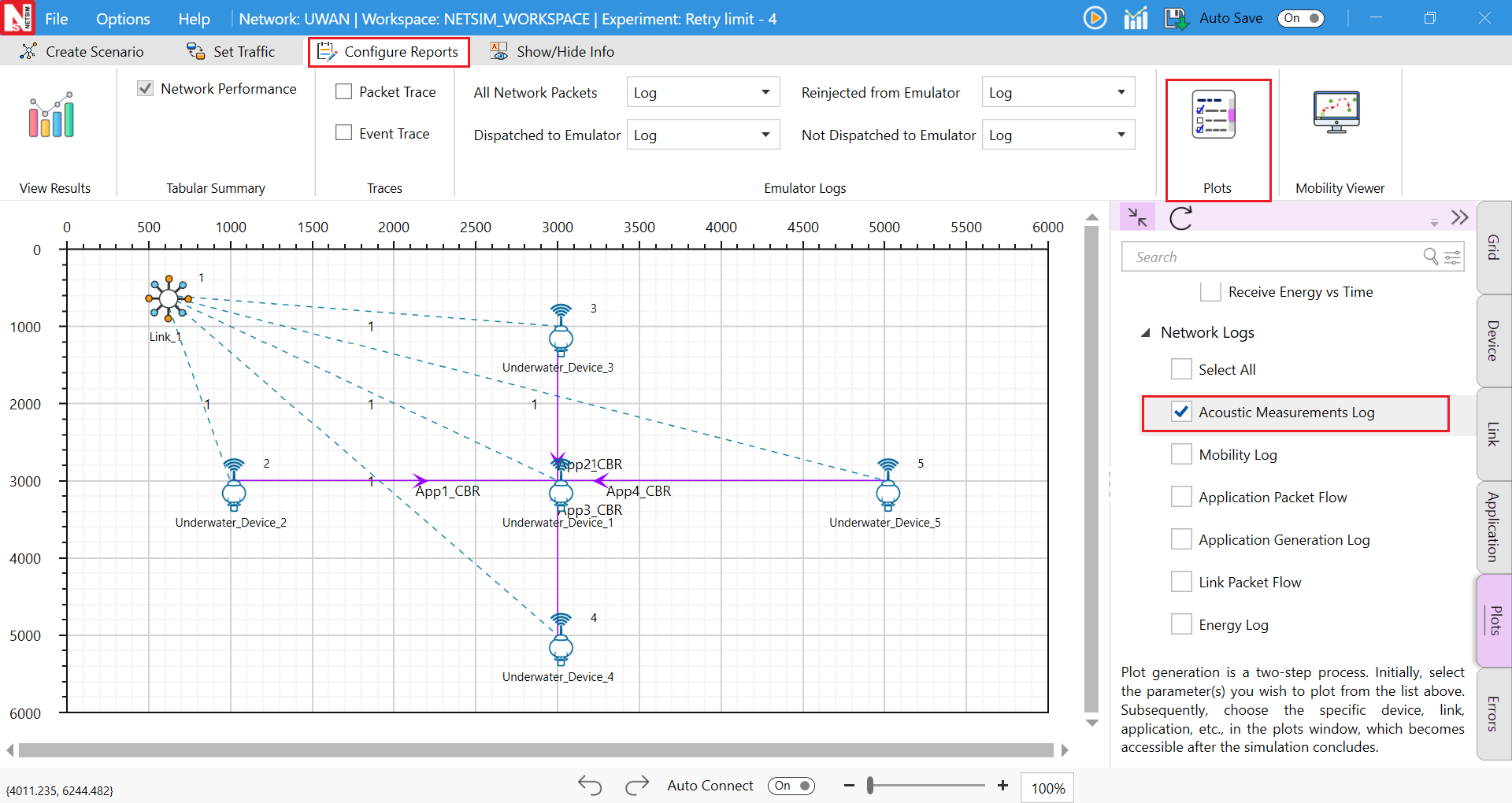
Similarly, users can enable the plots for Acoustic Measurements and energy.

GUI Configuration Parameters
The UWAN parameters can be accessed by right clicking on an Underwater device \(>\) selecting Open properties as new window \(>\) Interface (Acoustic) Properties Physical Layers.
| UWAN Properties | |||
|---|---|---|---|
| Interface (Acoustic) – Physical Layer | |||
| Parameter | Type | Range | Description |
| Source Level | Local | 170–225 dB// 1 \(\mu\)Pa, Default: 190 dB// 1 \(\mu\)Pa | It is the signal level of the transmitter. NetSim GUI takes source level, \(SL\), as the input, with units dB// 1 \(\mu\)Pa. In seawater, 1 W of radiated acoustic power creates a sound field of intensity 170.8 dB// 1 \(\mu\)Pa, 1m away from the source. For converting from electrical transmit power, in Watts (W), to \(SL\) in dB// 1 \(\mu\)Pa, the following equation can be used: \(SL = 10\log_{10}((\xi \times P_{tx}^{el})[W]) + 170.8\) |
| Antenna Gain (dBi) | Local | \(-1000\) to 1000 dBi | A relative measure of an antenna’s ability to direct or concentrate radio frequency energy in a particular direction or pattern. The measurement is typically measured in dBi. |
| Forward error correction coding (FEC) | Fixed | TRUE | FEC is used for controlling Error-Correcting code, in data over unreliable or noisy communication channels. This is always set to true and the SNR BER calculations factor in FEC. |
| Modulation | Local | QPSK, BPSK, FSK, 16QAM, 64QAM, 256QAM | Modulation is the process of varying one waveform in relation to another waveform. It is used to transfer data over an analog channel. |
| Coding Rate | Local | 1/2, 2/3, 3/4, 5/6 | It states what portion of the total amount of information is useful (non-redundant). This code rate is typically a fractional number. |
| Frequency | Local | 0.01–1000 kHz | The center frequency in the transmission bandwidth |
| Data rate (kbps) | Local | 0–255 kbps | It is the number of kilo-bits that are conveyed or processed per second |
| Receiver Sensitivity (dB) | Local | \(-120\) – 0 dBm, Default: \(-85\) dBm | It is the lowest power level at which the receiver can detect the acoustic signal and demodulate data. The interference threshold is equal to the receive sensitivity as explained in 3.1.8 |
| Bandwidth (Hz) | Local | 0–1000 Hz | Bandwidth is the range of frequencies occupied by acoustic signals. |