Simulation GUI
Open NetSim and click New Simulation 🡪 Cognitive Radio Networks as shown Figure-1.

Figure-1: NetSim Home Screen
Create Scenario
Cognitive Radio Networks come with a palette of various devices like CR CPE, Base Station L2 Switch, Router, Wired Node, Wireless Node, and AP (Access Point).
Click and drop into environment
Add a Base Station (BTS) – click the Base Station icon on the toolbar and place the BTS in the grid.
Add a Cognitive Radio CPE – click the CR CPE icon on the toolbar and place the CR CPE in the grid.
Add a Switch, Router, Wired Node, Wireless Node, and an Access point – click the appropriate icon on the toolbar and place the device in the grid.
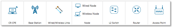
Figure-2: CR Networks Device Palette in GUI
NOTE: If you change the settings of the grid, then ensure that you place the CPE in the BS’s coverage area.
Connect the devices in the Cognitive Radio network by clicking the Wired/Wireless icon on the toolbar.
Configure an application as follows:
Click on the Set Traffic tab in the top ribbon/toolbar.
Select any application from the list and configure the traffic between source and destination.
Specify other application parameters per your model.
Set the properties of the BTS, CR CPE, and other devices as follows:
Click on a BTS, CR CPE, or device, then open the right-side properties panel and modify the interface and layer properties as per your requirements.
For a BTS, specify incumbent count, minimum and maximum frequency, channel bandwidth, modulation technique, coding rate.
Enable Packet Trace, Event Trace (Optional)
Click Packet Trace / Event Trace icon in the tool bar and click on OK button. For detailed help, please refer to sections 8.3 and 8.4 of the User Manual. Select Plots icon for enabling Plots and click on OK button see Figure-3.

Figure-3: Packet Trace, Event Trace & Plots options on top ribbon
GUI Configuration Properties
Base station |
|||
|---|---|---|---|
Base station-Interface(Wireless)-Datalink layer |
|||
Parameter |
Scope |
Range |
Description |
MAC address |
Fixed |
The MAC address is a unique value associated with a network adapter. This is also known as hardware address or physical address. This is a 12-digit hexadecimal number (48 bits in length). |
|
Duplexing |
Fixed |
Time Division Duplexing: In TDD the upstream and downstream transmissions occur at different times and share the same channel Frequency Division Duplexing: In FDD, there are different frequency bands used uplink and downlink. The UL and DL transmissions can occur simultaneously. |
|
Dsx Request Retries |
Local |
1-7 |
This message is sent either by a CPE or BS and is to create a new service flow, and shall not contain parameters for more than one service flow. Dynamic Service Change Requests A Dynamic Service Change Request (DSC-REQ) message is sent by a CPE or BS to dynamically change the parameters of an existing service flow. A DSC-REQ message shall carry parameters for only one service flow. A DSC-REQ message shall contain Service Flow parameters that specify the service flow’s new traffic characteristics and scheduling requirements. Dynamic Service Deletion Requests A Dynamic Service Deletion Request (DSD-REQ) is sent by a CPE or BS to delete an existing service flow. |
Dsx Response Retries |
Local |
1-7 |
Number of Timeout Retries on DSA/DSC/DSD Responses Dynamic Service Addition Responses A DSA-RSP message shall be generated in response to a received DSA-REQ message. If the transaction is successful, the DSA-RSP message may contain Service Flow parameter and CS parameter encodings. Dynamic Service Change Responses A DSC-RSP shall be generated in response to a received DSC-REQ message. If the transaction is successful, the DSC-RSP message may contain Service Flow parameters and CS parameter encodings. Dynamic Service Deletion Responses A DSD-RSP message shall be generated in response to a received DSD-REQ message. If the transaction is successful, the DSA-RSP message may contain Service Flow parameters and CS parameter encodings. |
T7 (S) |
Local |
0-1 |
Waiting Time for DSA/DSC/DSD Response timeout. |
T8 (ms) |
Local |
0-300 |
Waiting Time for DSA/DSC Acknowledge timeout. Maximum 300 ms. DSA/DSC Acknowledges are sent in response to the DSA-RSP/DSC-RSP Messages. |
T31 (ms) |
Local |
1-16 |
Waiting time for BLM-REP(Bulk Measurement Report) timeout. |
Channel Check Time (s) |
Local |
0-100 |
The time during which a channel shall be checked for the presence of licensed incumbent signals having a level above the Incumbent Detection Threshold prior to the commencement of WRAN operation in that channel, and in the case of TV, a related channel at an effective isotropic radiated power level that can affect the measured channel. |
Non Occupancy Period (s) |
Local |
1-60 |
The required period during which WRAN device transmissions shall not occur in a given channel because of the detected presence of an incumbent signal in that channel above the Incumbent Detection Threshold or, in the case of TV, above a given effective isotropic radiated power level. |
Channel Detection Time (s) |
Local |
0-2 |
The maximum time taken by a WRAN device to detect a licensed incumbent signal above the Incumbent Detection Threshold within a given channel during normal WRAN operation. |
Probability of false alarm |
Local |
0 to 1 |
Probability of false alarm denotes the probability of a CR user declaring that a Primary User is present when the spectrum is actually free. Obviously, for a good detection algorithm, the probability of detection should be as high as possible while the probability of false alarm should be as low as possible. The range of probability in theoretical value is calculated as 0 to 1 and in real world it ranges from 0 to 0.25 |
Channel Move time (s) |
Local |
0-2 |
This is the time a WRAN system takes to stop all interfering transmissions on the current channel when it detects a licensed signal above the Incumbent Detection Threshold. For TV signals, the system may instead lower its power output to the allowed level within the channel when a TV signal is detected in the same or a related channel. |
NUM Sensing Period |
Local |
0-127 |
The number of times a cognitive radio network will check for other signals (like licensed users) within a specific time window. |
Sensing Period Duration |
Local |
0-1023 |
Duration of sensing period field (in units of OFDM symbols) in a Sensing Window Specification Array entry. |
Sensing Period Interval |
Local |
0-2047 |
Sensing Period Interval is the time between each sensing check in a cognitive radio network. This interval is like a break between each check, and it determines how often the network pauses to listen for any licensed users (like TV broadcasts or other priority signals) on the frequency. |
Candidate Channel Refresh Time |
Local |
1-10 |
Maximum time interval allowed before sensing is performed on the candidate channel to ensure that no incumbents are detected. |
Backup Channel Refresh Time |
Local |
1-10 |
Maximum time interval allowed before sensing is performed on the backup channel to ensure that no incumbents are detected. |
Candidate Channel Transition Time |
Local |
1-100 |
Minimum time duration without detection of any incumbent for a candidate channel to transition to the backup channel. |
Wait Before Channel Move |
Local |
1-4096 |
Waiting time before which the BS moves to the first backup channel. This is used to make sure that all the CPEs are ready to move to the backup channel before BS switches operation to this backup channel. |
Sensing Mode |
Local |
0-2 |
Specifies which SSF (Spectrum Sensing Function) outputs are valid and in some cases it specifies the behavior of the SSF. |
ISO Country Code |
Local |
ISO Code of the Country. |
|
Incumbent Count |
Local |
0-3 |
It refers to the number of Incumbents |
Name |
Fixed |
Name of the incumbent (i.e., Primary user) |
|
ID |
Fixed |
Incumbent id is identification number of Primary user |
|
Longitude/X-coordinate |
Local |
Less than the grid max value |
The location of the device on the x-axis or horizontal axis in 'Grid view' and Longitude in 'Map view'. You can change the X-axis/ Longitude of this device. Make sure that you provide a positive number and set a coordinate value that is less than the grid maximum. |
Latitude/Y-coordinate |
Local |
Less than the grid max value |
The location of the device on Y-axis or horizontal axis in 'Grid view' and Latitude in 'Map view'. You can change the Y-axis/ Latitude of this device. Make sure that you provide a positive number and coordinate within the total grid size of your scenario. |
Z Coordinate |
Fixed |
The location of the device on Z-axis. Note: Z-axis is non-editable parameter. Currently we do not support 3D visualization in UI. However, this is accounted for in calculation of the distance between the devices for physical layer simulation. |
|
Operating Frequency Start |
Local |
54-862 |
Frequency at which incumbent starts. |
Operating Frequency End |
Local |
54-862 |
Frequency at which incumbent ends. |
ON Duration |
Local |
1-100000 |
This represents how much time incumbent operates. |
OFF Duration |
Local |
0-100000 |
Time gap between two successive incumbent operations. |
Keep Out Distance (m) |
Local |
1-500 |
The maximum distance at which secondary user can detect the primary user. This is the distance between incumbent and the CR-CPE. |
Operational Distribution |
Local |
Constant distribution: In this the output is constant value. Exponential Distribution: In this the output is a form of continuous probability distribution. The probability density function of an exponential distribution has the form,
\[f(X,\lambda) = \lambda e^{( - \lambda x)}\]
The inter-arrival times of a Poisson process is distributed exponentially. And Poisson processes are used to model random events. This value can be modified by the user. Uniform Distribution- The distribution outputs an arbitrary outcome that lies between certain bounds. The bounds are defined by the parameters, a and b, which are the minimum and maximum values. Normal Distribution- A normal distribution is sometimes informally called a bell curve and naturally occurs in many situations. The curve is symmetric at the center (i.e. around the mean). Exactly half of the values are to the left of center and exactly half the values are to the right. The distribution that resembles a bell. Technical description of the normal distribution is available in the NetSim manuals. |
|
Base station-Interface(Wireless)- Physical Layer |
|||
Channel bandwidth |
Local |
6,7,8 |
Frequency band used to transmit the data. Difference between Maximum frequency and Minimum frequency. |
Sampling Factor |
Fixed |
8/7 |
In this value, together with the bandwidth and the number of subcarriers used, helps determine the useful symbol time, which is the time during which data is transmitted. |
Modulation Technique |
Local |
QPSK, 16QAM, 64 QAM |
Modulation is the process of varying one waveform in relation to another waveform.It is used to transfer data over an analog channel (i.e radio link).QPSK consists of two-bit modulation symbols. QPSK modulation is less noise resistant than BPSK as it has a smaller immunity against interference. Quadrature Amplitude Modulation (QAM), is a method of combining two amplitude modulated (AM) signals into a single channel thereby increasing the effective bandwidth. 16QAM uses a 16-point constellation and the symbol size is 4 bits 64QAM uses a 64-point constellation and the symbol size is 6 bits. |
Coding Rate |
Local |
1/2, 2/3, 3/4, 5/6 |
It states what portion of the total amount of information that is useful(non-redundant). This code rate is typically a fractional number. If code rate is k/n then for every k bits of useful information, the other coder generates totally n bits of data of which n-k are redundant. |
Multiple Access |
Fixed |
OFDMA is a frequency-division multiplexing (FDM) scheme utilized as a digital multi-carrier modulation method. A large number of closely-spaced orthogonal sub-carriers are used to carry data. The data is divided into several parallel data streams or channels, one for each sub-carrier. Each sub-carrier is modulated with a conventional modulation scheme (such as Quadrature Amplitude Modulation or Phase Shift Keying) at a low symbol rate maintaining total data rates similar to conventional single-carrier modulation schemes in the same bandwidth. |
|
Transmit Power (Mw) |
Local |
1-5000 |
It is the signal intensity of the transmitter. The higher the power radiated by the transmitter's antenna the greater the reliability of the communications system. Unit = mW |
FFT Size |
Fixed |
The effect of fast Fourier transform (FFT) size on detecting narrowband signals is analyzed and appropriate FFT size is suggested to improve the probability of detection. |
|
Cyclic Prefix Factor |
Local |
1/4, 1/8, 1/16, 1/64 |
Specifies the size of the cyclic prefix used by the PHY in the frame transmissions in this superframe. |
Self-Coexistence |
Fixed |
No |
A state by which wireless communication systems of the same type can share a RF transmission channel in a common area while minimizing harmful interference to each other by the use of appropriate means. In the case of IEEE 802.22, this means coexistence of multiple nearby IEEE 802.22 cells in the frame transmissions in this superframe. |
DCD Interval (Downstream Channel Descriptor Interval) |
Fixed |
10 |
DCD Interval: The interval sets how often these messages are sent. For example, if the DCD Interval is set to 10 (seconds), it means the base station will send a DCD message every 10 seconds. |
UCD Interval (Upstream Channel Descriptor Interval) |
Fixed |
10 |
UCD Interval: The interval defines how often these messages are sent. For instance, if the UCD Interval is set to 10 (seconds), the base station will send a UCD message every 10 seconds. |
BW Req Backoff Start |
Local |
0-15 |
Initial size of BW Request opportunity used by CPEs to contend to send bandwidth requests to BS. |
BW Req Backoff End |
Local |
0-15 |
Final size of BW Request opportunity used by CPEs to contend to send bandwidth requests to BS. |
UCC Response wait time:math:`mathbf{(s)}` |
Local |
2 |
It is the waiting time of BS after it has sent the Channel Switch Request until it gets Channel Switch Response |
TTG (:math:`mathbf{mu s)}` Transmit/Receive Transition Gap |
Fixed |
210 |
TTG gap stands for Transmit Transition Gap. It is provided between downlink and uplink subframe. In each frame, a TTG shall be inserted between the downstream and upstream bursts to allow the CPE to switch between the receive mode and transmit mode and to absorb the signal propagation time for a distance of up to 30 km . |
Downlink to Uplink Ratio |
Local |
1:1, 2:2, 3:3, 4:4 |
It is the ratio of downlink to uplink transmission time. |
Intra Frame Quiet Period Cycle Length |
Local |
0-15 |
Specified in number of superframes, it indicates the spacing between the superframes for which the intra-frame quiet period specification is valid. If this field is set to 1, the Quiet Period Cycle repeats every superframe. If it is set to 2, the Quiet Period Cycle repeats every 2 superframes, etc. If this field is set to 0, no intra-frame quiet period is scheduled or the current intra-frame quiet period is cancelled. |
Intra Frame Quiet Period Bitmap |
Local |
Length>0 |
Valid only if Claimed Intra-frame Quiet Period Cycle Length >0. Valid for each superframes identified by the Claimed Intra-frame Quiet Period Cycle Length, each bit in the bitmap corresponds to one frame within each specified superframe. |
IFQP Duration(Symbols) |
Local |
1-16 |
Valid only if Claimed Intra-frame Quiet Period Cycle Length >0. If this field is set to a value different from 0, (zero): it indicates the number of symbols starting from the end of the frame during which no transmission will take place. |
Reference distance (m) |
Global |
0-10 |
\[PL = PL_{d0} + 10 \times n\ \times log\frac{d}{d_{0}}\]
PL : is the path loss at the reference distance d0. Unit: Decibel (dB) d :is the distance between the transmitter and the receiver \(\mathbf{d}_{\mathbf{0}}\ \): is the reference distance defined in the standard See propagation-model.pdf for more information n(eta) : is the path loss exponent |
CR-CPE-Interface(Wireless)- Datalink Layer |
|||
BLM REP Retries |
Local |
0-7 |
Number of retries allowed for sending BLM-REP. |
CR-CPE-Interface(Wireless)- Physical Layer |
|||
T20(MACframes) |
Local |
1-16 |
Time the CPE searches for preambles on a given channel. At the beginning of every superframe, the BS shall transmit the superframe preamble and the superframe control header on the operating channel using the modulation/coding. |
Antenna gain (dB) |
Local |
-1000 to 1000 |
A relative measure of an antenna’s ability to direct or concentrate radio frequency energy in a particular direction or pattern. The measurement is typically measured in dBi (Decibels relative to an isotropic radiator). |
Antenna height (m) |
Local |
1 to 100 |
Antenna height is only considered when using the following propagation models: Cost 231 Hata Urban, Cost 231 Hata Suburban, Hata Urban, Hata Suburban. These are propagation models used to model urban scenarios where the antenna height is an important parameter to compute the pathloss. When using these models, the antenna height represents the height of the antenna above the ground. Since these are urban scenarios, it is assumed that the nodes are always on the ground (i.e., z=0). |
Table-1: Datalink layer, physical layer properties of CR CPE and Base Sation.
Run Simulation
Click on Run Simulation icon on the top ribbon/toolbar.

Figure-4: Run Simulation on top ribbon.
Set the Simulation Time and click on the Run button.