Simulation GUI
Create Scenario
Open NetSim and click New Simulation → 5G NR as shown Figure-1.
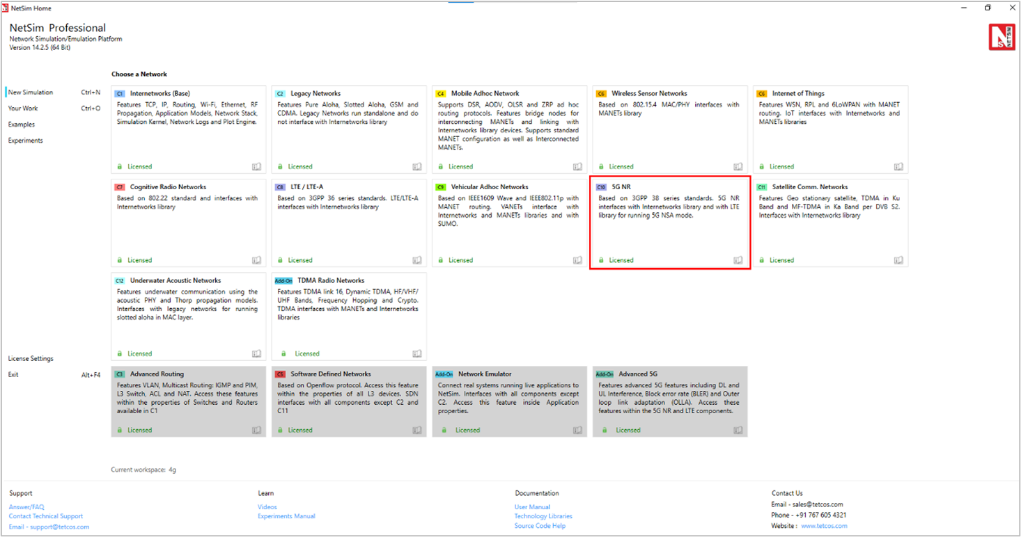
Figure-1: NetSim Home Screen
5G NR comes with a palette of various devices like Wired & Wireless Nodes, L2 Switch & Access Point, AMF (Access and Mobility Management Function), UPF (User Plane Function), SMF (Session Management Function) & Router, gNB (Equivalent of eNB in LTE), UE (User Equipment), and Building. Devices are connected using 3GPP defined interfaces; O-RAN defined interfaces are not available.
NetSim 5G Network Setup
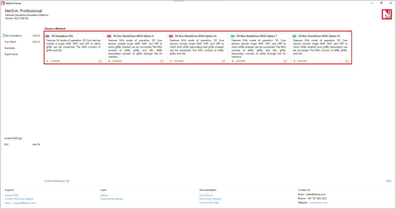
Figure-2: NetSim 5G Network Setup window
Deployment Architecture
The deployment options have been grouped into 2 categories. Standalone (SA) option where there is only one independent access network (5G NR) that is connected to the 5G Core and the Non-Standalone (NSA) options where both LTE and 5G NR radio access technologies are present, where one of the access networks assist the other in connecting to either an EPC or a 5G.
Stand Alone: In 5G Stand-alone mode of operation in NetSim, the network can be created using the 5G Core devices which includes a single AMF, SMF and UPF to which the gNB can be connected via Layer 2 Switches. The RAN part consists of gNBs and UEs and the UEs can handle both Uplink and Downlink data transfer to and from the Data Network (DN) via the UPF.
Non-Stand Alone: In the Non-Stand-alone mode of operation in NetSim, the users can design the network scenario using different deployment options.
The NSA modes in NetSim’s 5G module includes:
Option 4 where only 5G Core devices are present, and EPC is not available. Option 4 is categorized into:
Option 4: Only gNB connects to all the 5G Core interfaces. eNB connects to the XN interface.
Option 4a: gNB connects to all 5G Core interfaces and eNB connects to AMF and UPF through respective interfaces.
Option 7 where only 5G Core devices are present, and EPC is not available. Option 7 is categorized into:
Option 7: eNB connects to all 5G Core interfaces. gNB connects only to the XN interface.
Option 7a: gNB connects to AMF and UPF through the respective interfaces and eNB connects to all the 5G Core interfaces.
Device Placement
NetSim places the 5G core devices (AMF, SMF, UPF and Switches) / LTE EPC by default onto the grid.
Only one 5G Core and/or LTE EPC is currently supported.
Users cannot remove 5G Core devices and/or LTE EPC, or their interconnecting links.
Users may move these devices in the grid.
Users can drop gNBs/eNBs which get automatically connected to 5G Core. If a gNB/eNB is removed, the connected links to the core switches are automatically removed.
Users can drop UEs and must connect them to gNBs/eNBs via links.
IP addressing is automatically set by NetSim. It is recommended not to change the default IP addresses.
Note: In NSA Mode the UEs gets automatically connected to its master node. Only for secondary node UEs must be connected manually.
NSA Deployment Device Connectivity
The device connectivity rules are explained below. Example screenshots are available in section 3.16.
Option 4 / 4a
UE should mandatorily be connected to the master node (MN) first. In option 4, the MN is gNB
UE should mandatorily be connected to the secondary node (SN) next. In option 4, the SN is the eNB
UE cannot be connected to any other device.
The data (external) network connects to the 5G core through the UPF. This is achieved by first connecting a router (let’s call it R1) to the UPF.
Switches, nodes, APs and other routers can now be connected to R1
Connectivity rules for the devices within the data network follow the guidelines specified in the Internetwork library document.
Option 7 / 7a
UE should mandatorily be connected to the master node (MN) first. In option 7, the MN is eNB
UE should mandatorily be connected to the secondary node (SN) next. In option 7, the SN is the gNB
UE cannot be connected to any other device.
The data (external) network connects to the 5G core through the UPF. This is achieved by first connecting a router (let’s call it R1) to the UPF.
Switches, nodes, APs and other routers can now be connected to R1.
Connectivity rules for the devices within the data network follow the guidelines specified in the Internetwork library document.
Grid Settings
NetSim allows users to design the network on a rectangular grid. The major and minor grid lines are displayed; major grid line values along the X and Y coordinate are displayed. Each device’s X, Y coordinate is determined by its location on the grid.
Users can choose the grid size prior to placement of the first device.
Users can change the grid size after placing devices on the grid, but only if the new grid size is larger than the current grid size and the grid origin does not prevent the change.
The grid length can be in the range of 10 m to \(10^{9\ }\)m.
Devices Specific to NetSim 5G NR Library
UE: User Equipment.
Each UE has a single LTE NR interface with an infinite buffer. It can connect to a gNB (Base Station or BS) in both FR1 (μ-Wave) and FR2 (mm-Wave) bands.
A UE can be stationary or mobile.
The UE’s location is determined by its (X, Y) co-ordinate on the grid or by its (Lat, Lon) when using a map background.
gNB: This represents a base station (BS) with all the components i.e., antennas, radio, baseband, and the protocol stack. NetSim currently does not allow for the gNB to be split into RU, DU and CU.
NetSim supports 3 types of gNBs (i) Macro Cell gNB Omni Antenna (ii) Macro Cell gNB Sector Antenna and (iii) Small Cell gNB Omni Antenna. The macro cell gNBs by default have a transmit power setting of 40 dBm and operate in the FR1 3.5 GHz n78 band. The small cell gNBs have a transmit power setting of 30 dBm and operate in the FR2 28 GHz n261 band. Macro cell gNBs can be equipped with either omni-directional or sector antennas, and they are named based on their respective types.
It has a 5G RAN interface for wireless connectivity to UEs.
A gNB can be configured as a μ-Wave (FR1, sub 6GHz) or a mm-Wave (FR2) BS by appropriately selecting the frequency of operation.
It has a 5G N3 interface for wired connectivity to UPF through an L2 Switch,
It has a 5G N1 N2 interface for wired connectivity to AMF through an L2 Switch, and
It has a 5G XN interface for wired connectivity between the gNBs through an L2 Switch.
Every gNB has an infinite buffer.
UPF (User Plane Function): User Plane Function has 5G N4 interface for wired connectivity to SMF, 5G_N3 interface for wired connectivity to gNB through L2 Switch, and 5G N6 interface for wired connectivity to router in NG core which in turn can connect to Switches, APs, Servers etc
SMF (Session Management Function): Session Management Function has 5G N11 interface for wired connectivity to AMF and 5G N4 interface for wired connectivity to UPF.
AMF (Access and Mobility Management Function): Access and Mobility Management Function has 5G N11 interface for wired connectivity to SMF and 5G N1 N2 interface for wired connectivity to gNB’s through L2 Switch.
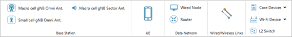
Figure-3: 5G NR Device Palette in GUI
Building: Users can place gNBs, UEs inside buildings to simulate indoor RF propagation effects.
To add building on the grid, go to options-> Configure Building.
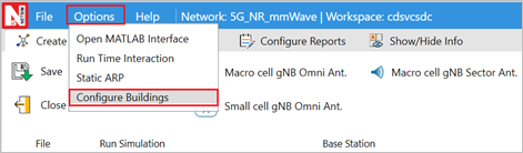
Figure-4: Configuring Building in GUI
Click on Add and set the building properties as required and click on configure. The building will be placed on a grid as per the settings.
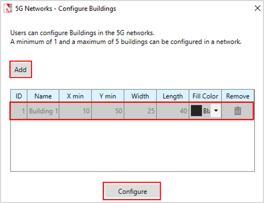
Figure-5: properties settings for building
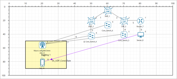
Figure-6: The screenshot displays the building as configured in the settings
GUI Parameters in 5G NR
The 5G NR parameters can be accessed by right clicking on a gNB or UE and selecting Interface Wireless (5G RAN) Properties -> Datalink and Physical Layers.
gNB Properties |
|||
|---|---|---|---|
Interface (5G RAN) – Data Link Layer |
|||
Parameter |
Type |
Range |
Description |
Scheduling Type |
Global |
Round Robin |
This is usually done to load balance and share system in circular order, handling all processes without priority |
Global |
Proportional Fair |
It is based upon maintaining a balance by trying to maximize total throughput while at the same time allowing all users at least a minimal level of service. |
|
Global |
Max Throughput |
Maximum throughput scheduling is a procedure to maximize the total throughput of the network by giving scheduling priority to the least "expensive" data flows. |
|
Global |
PFS with Rate Guarantee |
NetSim uses a proportional fair scheduling (PFS) algorithm in the gNB to provide guaranteed bit rate (GBR) services for user equipment (UEs) in both downlink (DL) and uplink (UL). It enables users to configure GBR while dynamically allocating resources to maintain the minimum required bit rate. |
|
Local |
Configuring GBR UEs |
NetSim uses a proprietary PF based scheduling algorithm in the gNB to provide Guaranteed Bit Rate (GBR) services for User Equipment (UEs) in both downlink (DL) and uplink (UL). Users can configure GBR for UEs and the algorithm dynamically allocates resources to maintain the minimum required bit rate. This option allows you to configure the rate guarantee for GBR UEs. |
|
Local |
GBR Bias Learning Rate |
The GBR Bias Learning rate means the “penalty” for not meeting a user’s throughput guarantee and is continuously adjusted based on the difference between achieved and guaranteed throughput. If the EWMA MAC throughput is below the guaranteed throughput, the Index Bias (Lagrange multiplier) increases, raising the user’s priority and allocating more resources. If the EWMA MAC throughput exceeds the guaranteed throughput, the Index Bias decreases, lowering the user’s priority and freeing resources for others. |
|
Local |
GBR UE Index Bias Maximum |
The maximum value the GBR Index Bias (Lagrange Multiplier) can range from 0 to 100. |
|
Slicing |
Global |
TRUE, FALSE |
Network slicing is a key technology in 5G networks that enables the efficient allocation of radio access network (RAN) resources to guarantee specific service level agreements (SLAs) for different service categories. This capability allows network operators to create multiple virtual networks, or "slices," on top of a shared physical infrastructure, each tailored to meet the diverse requirements of various use cases and applications This parameter allows users to enable/disable network slicing when simulating 5G. |
Resource Sharing Technique |
Global |
Static |
The Two resource sharing options are defined as Static (or Hard Slicing) and Dynamic (or Soft Slicing). Static Resource Sharing In this, slices are allocated a fixed percentage of resources. It supports eMBB, URLLC, MIoT, V2x slice types |
Dynamic |
Dynamic Resource Sharing In this, the resources sharing is handled by the algorithm dynamically – it uses PFS (Proportional Fair Scheduling) with a rate guarantee, using stochastic online learning. This algorithm is derived from non-linear optimization theory. |
||
EWMA Learning rate |
Local |
Default value: 0.02 ( Static), Dynamic ( 0.0005) Range: \(0.00000001\) (\(10^{- 8})\) to \(0.1\) (\(10^{- 1})\) |
EWMA Learning Rate (\(\alpha\)) determines how important the current observation is in the calculation of the EWMA. The expression below shows how the current throughput is based on the previous throughput and the current rate.
\[\theta_{t} = (1 - \alpha)\theta_{t - 1} + \alpha R_{t}\]
|
Lagrange multiplier learning rate |
Local |
Default value: 0.000005 Range: \(0.00000001\) (\(10^{- 8})\) to \(0.1\) (\(10^{- 1})\) |
The Lagrange multiplier measures the "penalty" for not meeting a user's throughput guarantee and is continuously adjusted based on the difference between achieved and guaranteed throughput. |
SSB Periodicity |
Local |
5, 10, 20, 40, 80, 160 ms |
It is a time interval between UE Measurement Report |
RRC MIB Period (ms) |
Local |
80 |
The UE needs to first decode MIB for it to receive other system information. MIB is transmitted on the DL-SCH (logical channel: BCCH) with a periodicity of 80 ms and variable transmission repetition periodicity within 80 ms. MIB packets can be seen in the NetSim packet trace post simulation under Control Packet type |
RRC SIB Period (ms) |
Local |
160 |
SIB1 also contains radio resource configuration information that is common for all UEs. SIB1 is transmitted on the DL-SCH (logical channel: BCCH) with a periodicity of 160 ms and variable transmission repetition periodicity within 160 ms. SIB1 is cell-specific. SIB1 packets can be seen in the NetSim packet trace post simulation under Control Packet type. |
PDCP Header Compression |
Local |
True / False |
Header compression of IP data flows using the ROHC protocol, Compresses all the static and dynamic fields. |
PDCP Discard Delay Timer |
Local |
50/150/300/500/750/ 1500 |
The discard Timer expires for a PDCP SDU, or the successful delivery of a PDCP SDU is confirmed by PDCP status report, the transmitting PDCP entity shall discard the PDCP SDU along with the corresponding PDCP Data PDU. |
PDCP Out of Order Delivery |
Local |
True / False |
Complete PDCP PDUs can be delivered out-of-order from RLC to PDCP. RLC delivers PDCP PDUs to PDCP after the PDU reassembling. It can be enabled or disabled by setting the value “TRUE” or “FALSE”. |
PDCP T Reordering Timer |
Local |
0-500 ms |
This timer is used by the receiving side of an AM RLC entity and receiving AM RLC entity in order to detect loss of RLC PDUs at lower layer. Unit=ms. PDCP reordering is always enabled if in sequence delivery to layers above PDCP is needed. Reordering Timer should be in between 0 to 500 msec. |
RLC T Status Prohibit |
Local |
0-2400 ms |
This timer is used by the receiving side of an AM RLC entity in order to prohibit transmission of a STATUS PDU. Unit=ms. |
RLC T Reassembly |
Local |
0-200 ms |
This timer is used by the receiving side of an AM RLC entity and receiving UM RLC entity in order to detect loss of RLC PDUs at lower layer. If t-Reassembly is running, t-Reassembly shall not be started additionally, i.e. only one t-Reassembly per RLC entity is running at a given time. Unit=ms. |
RLC T Poll Retransmit |
Local |
5-4000 ms |
This is used by the transmitting side of an AM RLC entity in order to retransmit a poll. |
RLC Poll Byte |
Local |
1kB-40 mB |
This parameter is used by the transmitting side of each AM RLC entity to trigger a poll for every pollByte bytes. |
RLC Poll PDU |
Local |
p4-p65536 (In multiples of 8) |
This parameter is used by the transmitting side of each AM RLC entity to trigger a poll for every pollPDU PDUs. |
RLC Max Retx Threshold |
Local |
t1, t2, t3, t4, t6, t8, t16, t32 |
This parameter is used by the transmitting side of each AM RLC entity to limit the number of retransmissions of an AMD PDU. |
HARQ Mode |
Local |
TRUE, FALSE |
Hybrid automatic repeat request (hybrid ARQ or HARQ) is a combination of re transmissions and error correction. The HARQ protocol runs in the MAC and PHY layers. In the 5G PHY, a code block group (CBG) is transmitted over the air by the transmitter to the receiver. If the CBG is successfully received the receiver sends back an ACK, else if the CBG is received in error the receiver sends back a NACK (negative ACK).If the transmitter receives an ACK, it sends the next CBG. However, if the transmitter receives a NACK, it re transmits the previously transmitted CBG. Large number packet errors can be observed in packet traces if HARQ is turned OFF. |
Max HARQ process count |
Local |
2,4,6,10,12,16 |
A HARQ entity is defined for each gNB-UE pair, separately for Uplink and Downlink and for each component carrier. The HARQ entity handles the HARQ processes. Max number of HARQ processes is 8 in 4G Max number of HARQ processes is 16 in 5G |
Max CBG per TB |
Local |
2,4,6,8 |
Each Transport block is split into Code blocks (CBs) and CBs are grouped into Code Block Groups (CBGs). A Code Block group can have up to 2/4/6/8 CBs. |
HARQ Retry Limit |
Local |
0-4s |
HARQ Retry Limit specifies the number of retransmissions attempts that will be made whenever a Code Block fails due to error. |
Handover Interruption time |
Global |
0-500ms |
The handover process in NetSim is based on event A3 i.e., the target signal strength is offset (3 dB) higher than the source signal strength. Handover interruption time (HIT) is added at the time of handover command is delivered to the UE. During this time there is no data plane traffic flow to the UE from the source/target. Handover interruption time can be varied from 0 to 500ms. |
Handover Margin |
Global |
0-10dB |
The handover margin is the offset in dB that is used as part of the event A3 handover process in NetSim. Handover is triggered when the target signal strength is offset higher than the source signal strength. Range for Handover margin is from 0.0 to 10.0 with 3.0 as default |
Time to Trigger |
Global |
0-5120ms |
With Time-to-Trigger, the handover is initiated only if the triggering requirement is fulfilled for a time interval specified by Time-to-Trigger (ms). This parameter can decrease the number of unnecessary handovers and effectively avoid Ping-Pong effects. 3GPP defines 16 valid values for time-to-trigger (all in milliseconds): 0, 40, 64, 80, 100, 128, 160, 256, 320, 480, 512, 640, 1024, 1280, 2560, and 5120. Users can enter any value between 0 to 5120 in milliseconds. |
Cell Individual Offset (CIO) |
Local |
–10 to +10 dB |
CIO is added to the measured SINR of the target cell during handover evaluation (\(SINR_{eff}\ = \ SINR_{actual}\ + \ CIO)\). A positive CIO increases the signal value and a negative CIO decreases the signal value. CIO is used to control handovers and distribute load across cells. |
NOTE: For detailed information on RLC, please refer RLC (Based on specification 38.322)
Interface (5G RAN) – Physical Layer |
|||
|---|---|---|---|
Parameter |
Type |
Range |
Description |
Protocol |
Fixed |
LTE NR (New Radio) is the 5G radio access technology. LTE-NR has the RLC and PDCP layers similar to LTE and has introduced a new layer named as SDAP (Service Data Adaptation Protocol). The frequency band for LTE NR is separated into two different frequency ranges: Frequency Range 1 (FR1) which includes sub-6 GHz bands and Frequency Range 2 (FR2) which includes mmWave bands. |
|
3GPP series |
Fixed |
NetSim 5G library is based on the 3GPP 38.xxx series. Some features in NetSim are per Rel 16 and some others are per Rel 17. |
|
Frame Duration (ms) |
Fixed |
10ms |
The length of the frame in milliseconds. The FRAME DURATION is a non-editable parameter whose value is fixed at 10 ms. |
Sub Frame Duration (ms) |
Fixed |
1ms |
The length of the frame in milliseconds. The SUBFRAME DURATION is a non-editable parameter whose value is fixed at 1 ms. |
Subcarrier Number Per PRB |
Fixed |
12 |
The number of Subcarriers per PRB is a non-editable parameter whose value is fixed at 12. |
gNB Height (m) |
Local |
1-150m |
Height of the base station (gNB) in meters. NetSim implements the 3GPP propagation models in which the Indoor gNB (placed within a building) range is 1 to 10 meters, while the Outdoor gNB range is 1 to 150 meters. NetSim only enforces the upper limit of 150m for both indoor and outdoor gNBs. |
TX Power (dBm) |
Local |
-40dBm to 100dBm |
In NetSim the Tx power range is -40dBm to 100dBm. The default value for Tx power is 23dBm for UEs and 40dBm for gNBs. When running in MIMO mode the transmit power is split equally amongst all the MIMO layers. The number of MIMO layers is Min (Nt, Nr). |
Duplex Mode |
Local |
TDD FDD |
Time Division Duplexing: Downlink (DL) and uplink (DL) transmissions are on the same frequency band but separated in time. Depending on the DL:UL ratio, slots are allocated for DL/UL transmissions. Frequency Division Duplexing: There are different frequency bands for UL and for DL. Hence UL and DL transmissions can occur simultaneously. NetSim supports both FDD and TDD bands and various CA configurations and Operating bands, for TDD and FDD, in FR1 and FR2 are available. |
CA Type |
Local |
Intra-band CA Intra-band contiguous CA CA Single Band Intra-band non-contiguous CA Single Band |
In Carrier aggregation (CA) multiple component carriers (CCs) are combined to usually increase the bandwidth, and thereby increase the bit rate. CA combinations are divided into intra-band (contiguous and non-contiguous) and inter-band. Intra-band contiguous CA configuration refers to contiguous carriers aggregated in the same operating band. Intra-band non-contiguous CA configuration refers to non-contiguous carriers aggregated in the same operating band. Inter-band CA configuration refers to the aggregation of component carriers in different operating bands, where the carriers aggregated in each band can be contiguous or non-contiguous. The Single Band drop-down options are per TS 38.101-1 for FR1 and 38.101-2 for FR2 |
CA Configuration |
Local |
Depends on CA Type |
The drop shows the frequency band options for the user to choose from. |
CA Count |
Fixed |
Depends on CA Type and CA Configurations |
This is a non-editable parameter that shows the number of component carriers based on the CA configuration. CA count would be 1 for Single Band configuration and will be greater than or equal to 2 for carrier aggregation. |
NOTE: For detailed information to Frequency Range (FR1 & FR2), Please, refer PHY Layer |
|||
Slot Type |
Local |
Mixed, Downlink, Uplink |
Slot type can be Mixed, Uplink, or Downlink. Mixed: In Mixed slot type, there will be both downlink and uplink slots allocated. The DL:UL ratio will determine how many slots are to be allocated for downlink and for uplink. The default value of the DL:UL ratio is 1:1 which can be then changed by the user. The setting is of the format x: y where x and y are integers. Uplink: In uplink slot type, there are only uplink slots, and the DL:UL ratio will be fixed by NetSim as 0:1. Note that uplink applications running TCP protocol will experience zero throughputs since there will be no downlink slots available for ACK transmissions Downlink: In downlink slot type, there are only downlink slots and the DL:UL ratio will be fixed by NetSim as 1:0. Note that downlink applications running TCP protocol will experience zero throughputs since there will be no uplink slots available for ACK transmissions |
Frequency Range |
Local |
FR1 & FR2 |
The frequency bands for 5G NR are separated into two frequency ranges. First, is Frequency Range 1 (FR1) which includes sub-6 GHz, frequency bands. The other is Frequency Range 2 (FR2) which includes frequency bands in the mmWave range. FR1: 410 MHz – 7125 MHz FR2-1: 24250 MHz – 52600 MHz FR2-2: 52600 MHz – 71000 MHz NetSim supports both FR1 and FR2. This is a non-editable parameter shown by NetSim based on the CA configuration chosen by the user. |
DL/UL Ratio |
Local |
a:b |
Represents the ratio in which slots are assigned to downlink and uplink transmissions. The value is in the form of a:b::DL:UL. Note that the ratio 1:0 or 0:1 might lead to NIL data transmissions since the initial attachment procedures require both UL and DL control packet transmissions. |
Operating Band |
Fixed |
n34, n38, n39, n40, n41, n50, n51, n77, n78, n79, n257, n258, n259, n260, n261, n262, n263 |
The operating band whose numbering is defined by 3GPP. This is a non-editable parameter (except for custom band) that is shown by NetSim based on the CA configuration chosen by the user. |
F Low (MHz) |
Fixed |
2010-4400 MHz |
The lowest frequency of the Uplink/Downlink operating band. This is a non-editable parameter (except for custom band) shown by NetSim based on the CA configuration chosen by the user |
F High (MHz) |
Fixed |
2025-5000 MHz |
The highest frequency of the Uplink/Downlink operating band. This is a non-editable parameter shown by NetSim based on the CA configuration chosen by the user |
Numerology |
Local |
µ = 0, 1, 2, 3, 5, 6 |
Sub carrier spacing is derived from numerology per the expression \(\mathrm{\Delta}f = 2^{\mu} \times 15kHz\). Thus, Numerology = 0 means subcarrier spacing 15 kHz Numerology = 1 means subcarrier spacing 30 kHz Numerology = 2 means subcarrier spacing 60 kHz Numerology = 3 means subcarrier spacing 120 kHz Numerology = 5 means subcarrier spacing 480 kHz Numerology = 6 means subcarrier spacing 960 kHz |
Channel Bandwidth (MHz) |
Local |
5-2000 MHz |
The bandwidth can vary from 5 MHz to 100 MHz for TDD bands in FR1 frequency range and 50 MHz to 2000 MHz for TDD bands in FR2 frequency range. The bandwidth is 5MHz to 40 MHz in case of FDD bands. Unit is MHz |
PRB Count |
Local |
PRB stands for physical resource block. The PRB count is dependent on Channel Bandwidth and automatically determined by NetSim. It cannot be edited in the GUI. |
|
Guard Band (KHz) |
Local |
242.5 - 147040 kHz |
Guard band is the unused part of the radio spectrum between radio bands, for the purpose of preventing interference. The minimum guard bands are calculated using the following equation: (\(BWChannel\ x\ 1000\ (kHz)\ - \ NRB\ \ x\ SCS\ x\ 12)\ /\ 2\ - \ SCS/2.\ Unit\ is\ kHz.\) |
Subcarrier Spacing |
Local |
15 - 960 kHz |
In 5G NR, subcarrier spacing of 15, 30, 60, 120, 240,480,960 KHz are supported. Subcarrier spacing \(= 15kHz\ (µ\ = \ 0)\) Subcarrier spacing \(= 30kHz\ (µ\ = \ 1)\) Subcarrier spacing \(= 60kHz\ (µ\ = \ 2)\) Subcarrier spacing \(= 120kHz\ (µ = 3)\ \) Subcarrier spacing \(= 240kHz\ (µ = 4)\ \) Subcarrier spacing \(= 480kHz\ (µ = 5)\) Subcarrier spacing \(= 960kHz\ (µ = 6).\) |
Bandwidth PRB |
Local |
180 - 11520 kHz |
The PRB bandwidth is dependent on numerology (μ) as shown below. \(Unit\ = \ kHz.\) Bandwidth\(= 180\ kHz\ (\mu = 0)\) Bandwidth\(= 360\ kHz\ (\mu = 1)\) Bandwidth\(= 720\ kHz\ (\mu = 2)\) Bandwidth\(= 1440\ kHz\ (\mu = \ 3)\) Bandwidth\(= 2880\ kHz\ (\mu = 4)\) Bandwidth\(= 5760\ kHz\ (\mu = 5)\) Bandwidth\(= 11520\ kHz\ (\mu = 6)\) |
Slot per Frame |
Local |
10, 20, 40, 80, 160, 320, 640 |
This represents the number of slots in a frame and is a non-editable parameter. NetSim determines the slots per frame, based on the selected numerology, in the following way When μ= 0, a subframe has only one slot, and frame has 10 slots. When μ= 1, a subframe has 2 slots, and a radio frame has 20 slots. When μ= 2, In this configuration, a subframe has 4 slots in it, which means a radio frame contains 40 slots in it. When μ= 3, In this configuration, a subframe has 8 slots in it, which means a radio frame contains 80 slots in it. When μ= 4, In this configuration, a subframe has 16 slots in it, which means a radio frame contains 160 slots in it. When μ= 5, In this configuration, a subframe has 32 slots in it, which means a radio frame contains 320 slots in it. When μ= 6, In this configuration, a subframe has 64 slots in it, which means a radio frame contains 640 slots in it. |
Slot per Subframe |
Local |
1, 2, 4, 8, 16, 32, 64 |
This represents the number of slots in a sub-frame and is a non-editable parameter. NetSim determines the slots per sub-frame, based on the selected numerology, in the following way When μ= 0, a subframe has only one slot When μ= 1, a subframe has 2 slots. When μ= 2, In this configuration, a subframe has 4 slots in it. When μ= 3, In this configuration, a subframe has 8 slots in it. When μ= 4, In this configuration, a subframe has 16 slots in it. When μ= 5, In this configuration, a subframe has 32 slots in it. When μ= 6, In this configuration, a subframe has 64 slots in it. |
Slot Duration (μs) |
Local |
1000, 500, 250, 125, 62.5, 31.25, 15.63 μs |
Slot duration is a non-editable parameter that depends on numerology selected. μ= 0, Slot Duration = 1000 μs μ= 1, Slot Duration = 500 μs μ= 2, Slot Duration = 250 μs μ= 3, Slot Duration = 125 μs μ= 4, Slot Duration = 62.5 μs μ= 5, Slot Duration = 31.25 μs μ= 6, Slot Duration = 15.63 μs |
Cyclic Prefix |
Local |
Normal |
If the cyclic prefix is set to "normal" then the number of symbols per slot is 14, if it is set to "extended" then the number of symbols per slot is 12. All carriers have the "normal" option while only certain carriers have the "extended" option. |
NOTE: Cyclic Prefix is Extended only for a few CA types. |
|||
Symbol per Slot |
Local |
12, 14 |
Symbol Per Slot is dependent on Cyclic prefix. If cyclic prefix is set to "Normal" then Symbol Per Slot = 14 If cyclic prefix is set to "Extended" then Symbol Per Slot = 12 |
Overhead (%) per DL slot |
Local |
0.01-0.99 |
This represents the fraction of symbols in a slot used for control signaling. The remaining fraction is used for data transmission. In NetSim calculations are done over aggregated PRBs per the formula given below: Data PRB available = Total PRB available - Ceil(Total PRB available×Overhead Fraction) DL Fraction range 0.01 to 0.99 Default: 0.14 for FR1, 0.18 for FR2 In 4G Network the default value is 0.25 for both FR1 and FR2. |
Overhead (%) per UL slot |
Local |
0.01-0.99 |
This represents the fraction of symbols in a slot used for control signalling. The remaining fraction is used for data transmission. In NetSim calculations are done over aggregated PRBs per the formula given below: Data PRB available = Total PRB available - Ceil(Total PRB available * Overhead Fraction) UL Fraction range 0.01 to 0.99 Default: 0.08 for FR1, 0.10 for FR2 In 4G Network the default value is 0.25 for both FR1 and FR2. |
Symbol Duration (μs) |
Local |
71.43, 35.71, 17.86, 8.93, 4.47, 2.23, 1.12 |
Symbol duration is a non editable parameter that depends the numerology selected When \(\mu\ = \ 0\), symbol duration = \(71.43\ \mu s\ \) When \(\mu\ = \ 1\), symbol duration \(= \ 35.71\ \mu s\ \) When \(\mu\ = \ 2,\) symbol duration \(= \ 17.86\ \mu s\ \) When \(\mu\ = \ 3\), symbol duration \(= \ 8.93\ \mu s\ \) When \(\mu\ = \ 4\), symbol duration \(= \ 4.47\ \mu s\) When \(\mu\ = \ 5\), symbol duration \(= \ 2.23\ \mu s\) When \(\mu\ = \ 6\), symbol duration \(= \ 1.12\ \mu s\) |
ANTENNA |
|||
|---|---|---|---|
TX Antenna Count |
Local |
1, 2, 4, 8, 16, 32, 64, 128 in gNB (1, 2, 4, 8, 16 in UE) |
The number of transmit antennas. This parameter taken effect during MIMO operation; the number of MIMO layers would be Min (\(Nt,\ Nr\)), where \(Nt\) is the transmit antenna count at the transmitter and Nr is the receive antenna count at the receiver. The layer wise gains depend on the fading model chosen and is explained in the 5G NR manual, digital beamforming section. |
RX Antenna Count |
Local |
1, 2, 4, 8, 16, 32, 64, 128 in gNB (1, 2, 4, 8, 16 in UE) |
The number of received antennas. This parameter taken effect during MIMO operation; the number of MIMO layers would be Min (\(Nt,\ Nr\)), where \(Nt\) is the transmit antenna count at the transmitter and Nr is the received antenna count at the receiver. The layer wise gains depend on the fading model chosen and is explained in the 5G NR manual, digital beamforming section. |
Antenna Type |
Fixed |
NetSim supports two types of Antenna, Omnidirectional and Sector Antennas. |
|
Orientation Angle |
Local |
0-360\({^\circ}\) |
NetSim implements a 2D parabolic sector antenna as per 3GPP TR 37.840. The boresight angle denotes the direction of maximum gain, or the highest radiated power. The angle is defined to start at 0 from the positive X-axis. If positive Y points downward, the angle increases on clockwise rotation from the positive X-axis. If positive Y points upward, the angle increases in an anti-clockwise direction from the positive X-axis. The units for the boresight angle are in degrees. |
Element Gain |
Local |
-50 to +50 |
This is the maximum directional gain of the radiation element (in dB). The default value is 8 dBi. |
Front to back ratio |
Local |
10-40 |
The ratio of power gain between the front and rear of a directional antenna. |
Beam width |
Local |
0-90 |
The 3 dB, or half power, beamwidth of the antenna is defined as the angular width of the radiation pattern, between points 3 dB down from maximum beam level (beam peak). |
PDSCH CONFIG |
|||
MCS Table |
Local |
QAM64, QAM256, QAM64LOWSE |
MCS Table stands for modulation and coding scheme Table. The selection options are QAM64, QAM 256, and QAM64LOWSE. We recommend users set the same MCS table for PDSCH and PUSCH. The appropriate CQI table setting would be as follows: For QAM64 - Table1 For QAM256 - Table 2 For QAM64 LOWSE - Table 3 |
X Overhead |
Local |
XOH0, XOH6, XOH12, XOH18 |
Accounts for overhead from CSI-RS, CORESET, etc. If the xOverhead in PDSCH-ServingCellconfig is not configured (a value from 0, 6, 12, or 18), \(N_{oh}^{PRB}\) the is set to 0. |
PUSCH CONFIG |
|||
MCS Table |
Local |
QAM64, QAM256, QAM64 LOWSE |
MCS Table stands for modulation and coding scheme Table. The selection options are QAM64, QAM 256, and QAM64LOWSE. We recommend users set the same MCS table for PDSCH and PUSCH. The appropriate CQI table setting would be as follows: For QAM64 - Table1 For QAM256 - Table 2 For QAM64LOWSE - Table 3 |
Transform Precoding |
Local |
Enable/Disable |
Transform Precoding is the first step to create a DFT-s-OFDM waveform. Transform Precoding is to spread UL data in a special way to reduce PAPR (Peak-to-Average Power Ratio) of the waveform. In terms of mathematics, Transform Precoding is just a form of DFT(Digital Fourier Transform). |
CSIREPORT CONFIG |
|||
CQI Table |
Local |
Table1, Table2, Table3 |
The CQI indices and their interpretations are chosen from Table 1 or Table 3 for reporting CQI based on QPSK, 16QAM, and 64QAM. The CQI indices and their interpretations are chosen from Table 2 for reporting CQI based on QPSK, 16QAM, 64QAM and 256QAM. This is based on 3GPP Table 5.2.2.1-2, Table 1, Table 2 and Table 3. Users must set the MCS and CQI tables in the following combination QAM64: CQI Table 1 QAM 256: CQI Table 2 QAM 64 LOWSE: CQI Table 3 |
CHANNEL MODEL |
|||
Pathloss Model |
Local |
3GPP TR 38.901-7.4.1 Log Distance None |
NetSim computes signal attenuation per the mean pathloss model. The options currently available at None, 3GPP based and Log distance. |
Outdoor Scenario |
Local |
Rural Macro (RMa) Urban Macro (UMa) Urban Micro (UMi) |
There are three types of outdoor scenarios possible namely: Rural Macro, Urban Macro, and Urban Micro, as defined in the 3GPP TR 38.900 standard. The propagation characteristics of these scenarios are provided in the 5G NR Technology library manual, section Propagation Models. |
Building Height (m) |
Local |
5-50m |
Height of building in meters. Range is 5m to 50m. The building height can be varied in scenarios where UEs are placed inside the building and where the pathloss and other parameters are to be evaluated. The impact of building height can be seen in outdoor scenarios per formulas provided in the 5G NR Technology library manual, section Propagation Models (Per 3GPP TR 38.900 Channel Model) |
Street Width (m) |
Local |
5-50m |
Width of the street in meters. Range is 5 to 50 meters. The impact of street width can be seen in outdoor scenarios and will be per formulas provided in the 5G NR Technology library manual, section Propagation Models (Per 3GPP TR 38.900 Channel Model) |
Indoor Scenario |
Fixed |
Indoor Office |
This is a scenario where gNB and UE are within an indoor building |
Indoor Office Type |
Local |
Mixed-Office Open-Office |
There are two types of Indoor Office (InH): Mixed-Office, and Open-Office. An indoor scenarios is defined as one where we have both gNBs and UEs present within a building. Path-loss is higher than an Open-Office scenario. |
LOS/NLOS Selection |
Fixed |
3GPP TR 38.901-Table 7.4.2-1 Used Defined |
3GPP TR 38.901-Table7.4.2-1 The LOS mode, either Line-of-sight or Non-Line-of-sight is based on LOS probability calculated per the TR 38_901_Standard Table7.4.2-1 User Defined LOS probability is not per standard but is based on user input. NetSim will determine whether a device is in line-of-sight or non-line-of-sight based on the LOS probability value set by the user. |
LOS Probability |
Local |
0 to 1 |
LOS Probability defines the LOS mode. If LOS Probability=1, the LOS mode is set to Line-of-Sight explicitly and if the LOS Probability=0, the LOS mode is set to Non-Line-of-Sight explicitly. For, any value between 0-1 LOS mode is set per the given probability, by tossing a biased coin. |
Shadow Fading Model |
Local |
None 3GPP TR 38.901 |
Models for signal attenuation due to shadowing. 3GPP TR 38.901: 3GPP TR 38.901 model is suitable for a scenario with mobility and obstructions within the propagation environment. In this model, the shadowing value follows a log-normal distribution with a user specified standard deviation. In general, this value should be in the range of 5 to 12 dB depending on the density of obstructions within the propagation environment. None: To disable the Shadow fading Model. |
Fading and Beamforming |
Local |
No Fading MIMO unit gain, No fading MIMO array gain, Rayleigh with Eigen beamforming Rician with Eigen beamforming |
RAYLEIGH WITH EIGEN BEAMFORMING: When fading and beamforming is enabled, NetSim uses the rich scattering in the channel to form spatial channels. The number of spatial channels is equal to the number of layers (in turn equal to Min (\(Nt,\ Nr\))). The beamforming gains in the spatial channel is equal to the eigenvalues of the channel covariance (Wishart) matrix. When running in SISO (\(N_{t} = N_{r} = 1)\) this simply simulates Rayleigh fading. No fading MIMO unit gain: No fading with gain equal to unity (0 dB) No fading MIMO array gain: No fading but gain equals \(Min\ (N_{t},\ N_{r})\) See Table 3‑2 for more information. RICIAN WITH EIGEN BEAMFORMING: In Rician fading, the channel combines a dominant Line-of-Sight (LoS) component with scattered (Rayleigh) components. NetSim forms spatial channels equal to Min (N_t , N_r ) layers, with beamforming gains set by the eigenvalues of the Rician channel covariance matrix. The dominant eigenvalue (strongest layer) is boosted by the LoS path, delivering higher gains than Rayleigh fading, particularly in strong LoS scenarios. For SISO (N_t =N_r =1), this reduces to Rician fading with a defined K-factor (LoS-to-scattered power ratio). |
O2I Building Penetration Model |
Local |
None, Low Loss Model, High Loss Model, |
A model for signal attenuation due to Path-loss combined with fading, shadowing and O2I loss. The O2I loss is the Outdoor-to-Indoor penetration loss where the signal attenuates when it penetrates through structures like concrete walls, glass, wood etc. Low-loss model is applicable to RMa. High-loss model is applicable to UMa and UMi. None to disable the O2I loss.. |
Additional Loss Model |
Local |
None, Matlab |
Additional loss models can be set to NONE or MATLAB. If set to MATLAB then MATLAB will be automatically called by NetSim during execution. Note: NetSim Academic version does not support MATLAB. |
Pathloss Exponent (η) |
Local |
2 to 5 |
Pathloss exponent indicates the rate at which the pathloss increases with distance. The value depends on the specific propagation environment. Set any value between 2 to 5. |
Shadowing Model |
Local |
None, Log Normal |
Constant: A shadowing model is used to represent the signal attenuation caused by obstructions along the propagation path. The constant shadowing model is suitable for scenarios without mobility where the obstructions along the propagation paths remain unchanged. Log Normal: The lognormal shadowing model is suitable for a scenario with mobility and obstructions within the propagation environment. In this model, the shadowing value follows a log-normal distribution with a user specified standard deviation. In general, this value should be in the range of 5 to 12 dB depending on the density of obstructions within the propagation environment. |
Standard Deviation (dB) |
Local |
5 to 12 dB |
Shadowing is caused mainly by terrain features of the radio propagation environment. The mathematical model for shadowing is a log-normal distribution with standard deviation of 5 to 12 dB. Set any value between 5 to 12 dB. |
INTERFERENCE MODEL |
|||
Downlink Interference Model |
Global |
No interference, Graded distance, Based Wyner model,
Exact geometric model
|
DL interference options are No interference, Graded Distance based Wyner model and Exact geometric models. If no interference is chosen then in the SINR calculations, the value of I is set to -1000. Wyner and geometric models compute interference. Wyner is an approximate model used by the research community while the geometric model is exact. Technical details of the two models are provided in the 5G NR/4G manual. |
Uplink Interference Model |
Global |
No interference, Interference over thermal |
NetSim uses Interference-over-thermal (IoT), to model co-channel uplink interference.. |
IoT value (dB) |
Global |
0 to 20 |
The Uplink IoT (dB) value is used to compute the SINR, and Interference power based on the following equations: \(SINR\ (dB)\ = \ SNR(dB)\ - \ IoT(dB)\) The interference power (dBm units), logged in the radio measurements file will be given as
\[I\ (dBm) = \ 10 \times \ log_{10}\ \left( N\ \times \ \left( 10^{IOT\ (dB) - 1} \right) \right)\]
where N is thermal noise and is equal to \(k \times TB\). |
ERROR MODEL AND MCS SELECTION |
|||
MCS selection model |
Global |
Ideal Shannon theorem-based rate, Shannon rate with attenuation factor |
NetSim determines the modulation and coding scheme in 5G and LTE, based on received SINR, per the following models: Ideal Shannon Theorem-Based Rate: Spectral Efficiency is computed as
\[Spectral\ Efficiency\ = \ log(1 + SINR)\]
Shannon Rate with Attenuation Factor \((\alpha)\): Spectral Efficiency is computed as
\[Spectral\ Efficiency\ = \ \alpha\ x\ log(1 + SINR)\]
Then the 3GPP standards Spectral Efficiency vs MCS Table is looked up to select the MCS. This could be the 64QAM table, 256 QAM table, or the 64QAMLOWSE table depending on what was chosen by the user. |
Attenuation Factor |
Global |
0.5-1 |
Attenuation factor \((\alpha)\) takes values between 0.5 and 1 with the default value of 0.75. |
BLER Model |
Global |
Zero BLER, BLER enable |
Block Error Rate Model (BLER) is used to decide code block and transport block errors in 5G and LTE. If set to true then NetSim looks up the SINR-CBS-MCS vs. BLER tables to decide on the code block error rate for the chosen MCS. Here MCS will be chosen as explained in the MCS selection section. If OLLA is enabled then MCS bump up/down will be based on HARQ ACKs/NACKs. |
Outer loop link adaptation |
Global |
TRUE FALSE |
The Outer Loop Link Adaptation (OLLA) technique, if enabled can improve the channel quality estimation by adjusting the value of SINR by an offset dependent on whether previous transmissions were decoded successfully or not, as captured by Hybrid Automatic Repeat Request (HARQ) feedback |
Target BLER |
Global |
0-1 |
The OLLA algorithm in NetSim is designed to converge the transport BLER to the set value of the target BLER. Range: 0 to 1 |
Propagation Model: Refer mmWave Propagation Models (Per 3GPP TR 38.900 Channel Model) for technical information. |
|||
UE Properties |
|||
|---|---|---|---|
Interface (5G_RAN) – Physical Layer |
|||
Parameter |
Type |
Range |
Description |
UE Height (m) |
Local |
1 - 22.5 |
It is the height of the UE in meters. |
TX Power (dBm) |
Local |
-40 dBm to 50 dBm |
In NetSim the Tx power range is -40dBm to 50dBm. The default value for Tx power is 23dBm for UEs and 40dBm for gNBs. When running in MIMO mode the transmit power is split equally amongst all the MIMO layers. The number of MIMO layers is Min (Nt, Nr). |
ANTENNA |
|||
TX Antenna Count |
Local |
1, 2 , 4, 8, 16 |
The number of transmit antennas. This parameter took effect during MIMO operation; the number of MIMO layers would be Min (Nt, Nr), where Nt is the transmit antenna count at the transmitter and Nr is the receive antenna count at the receiver. The layer wise gains depend on the fading model chosen and is explained in the 5G NR manual, digital beamforming section. |
RX Antenna Count |
Local |
1, 2, 4, 8, 16 |
The number of received antennas. This parameter took effect during MIMO operation; the number of MIMO layers would be Min (Nt, Nr), where Nt is the transmit antenna count at the transmitter and Nr is the receive antenna count at the receiver. The layer wise gains depend on the fading model chosen and is explained in the 5G NR manual, digital beamforming section. |
5G Logs |
|||
Parameter |
Type |
Range |
Description |
LTENR Radio Measurements Log |
Global |
Enable or Disable |
The LTENR Radio measurements csv log file records Timestamp, Device ID, Distance, Pathloss, Shadow fading loss, Received power, SNR, Interference Power, SINR, MCS, CQI, Beamforming gain and more, for each carrier on the PDSCH, PUSCH and SSB. PDSCH and PUSCH measurements are logged every sub-frame while SSB measurements are logged every UE measurement report. |
LTENR Resource Allocation Log |
Global |
Enable or Disable |
The 5G Radio Resource Allocation csv log file records information related to physical resource block (PRB) allocation such as the Total PRBs, Slot Start Time(ms), Slot End, BitsPerPRB, BufferFill, Allocated PRBs, Rank (scheduling metric) and more, in the DL and in the UL. All these parameters are written in every slot. |
LTENR Handover TTT Log |
Global |
Enable or Disable |
Records the events that occur during a handover. This contains the timestamp, serving cell ID, UE ID, target cell ID, and Handover Trigger time (time at which the handover condition was met) - when the TTT parameter is enabled. The log can be used to identify handover attempts and the impact of TTT on handovers. |
LTENR Code Block Log |
Global |
Enable or Disable |
Records parameters associated with Code Block segmentation such as Process ID, TB size, Modulation, Code Rate, CBS, BLER, CBG ID, etc. along with remarks on events associated with HARQ and PRB allocation. This will be useful to understand BLER model and Code Block segmentation in 5G. |
LTENR OLLA Log |
Global |
Enable or Disable |
Logs parameters associated with Outer Loop Link Adaptation(OLLA) such as CQI with and without OLLA, phy SINR, SINR Delta, Virtual SINR, etc along with time stamps, gNB ID, UE ID , etc. This log can be used to understand OLLA mechanisms in 5G. |
IEEE 802.11 Radio Measurement Log |
Global |
Enable or Disable |
Records pathloss, shadowing loss, fading loss, transmitted power, received power, SNR, Interference Power, SINR, SNR, BER, NSS, MCS, etc. This log can be used to understand the channel model and its impact on varying channel conditions. |
IEEE 802.11 Backoff Log |
Global |
Enable or Disable |
Records details such as the Device name, Time stamp, Packet ID, BackoffTime, contention Window size and Retry Limit. This log can be used to understand the Medium access mechanism in IEEE 802.11 Protocols. |
IEEE 802.11 Log |
Global |
Enable or Disable |
Records events and states associated with IEEE 802.11 protocols along with time stamps. This file can be used for understanding and debugging through the protocol internals. |
OSPF Log |
Global |
Enable or Disable |
Records events and states associated with the OSPF Protocol, such as the control message exchanges, interface state update, etc along with timestamps |
OSPF Hello Log |
Global |
Enable or Disable |
Logs the events associated with OSPF Hello messages with timestamps. This includes hello interval timer events, hello message update, hello message processing, etc. |
TCP Log |
Global |
Enable or Disable |
Records events associated with TCP connection states such as Listen, Syn-sent, Syn-received, Established, Fin-wait-1, Fin-wait-2, Close-wait, Closing, Last-ack, Time-wait, and Closed. |
PRB Utilization log |
Global |
Enable or Disable |
NetSim LTENR PRB Utilization Log records the parameters associated with PRB Utilization, including the proportion of PRBs used out of the total PRBs available, along with timestamps. This log tracks changes in PRB utilization over time, providing data on network load. It can identify patterns such as usage times, congestion or periods of under-utilization, helping to understand PRB allocation mechanisms in 5G. |
TCP Congestion window log |
Records events and states related to the TCP congestion window. The log includes timestamps and details such as source and destination devices, socket addresses, sender window sizes, and transmission events. It is useful for diagnosing TCP performance issues, monitoring flow control, and optimizing network efficiency. |
||
Table-1: 5G Config Properties
Devices: Click and drop into environment
AMF, UPF, and SMF:
Exactly one set of these devices are automatically placed by NetSim into the environment and connected appropriately to switches.
These devices are part of the 5G core.
These devices which are placed onto the environment cannot be deleted by the user.
Add a gNB(Macro cell gNB Omni Antenna, Small cell gNB Omni Antenna and Macro Cell Sector Antenna):
Click the gNB icon on the toolbar and place the gNB in the grid it will automatically connect to the L2_Switches connected to the AMF and UPF. The logical connectivity of the different interfaces (Xn, N1-N2, and N3) are broken out into different physical links.
gNBs can also be placed inside the building based on the network scenario created.
Every gNB should be connected to at least one UE.
Add a User Equipment (UE):
Click the UE icon on the toolbar and place the UE in the grid.
In SA & NSA mode UEs will get automatically connected to Master nodes while for the secondary nodes UEs should be connected manually.
UE’s can also be placed inside the building based on the network scenario created. The UE’s are always assumed to be connected to one gNB.
A UE can never be connected to more than one gNB, and neither can it be out-of-range of all gNBs.
Add a Router: A Router is automatically placed with the 5G Core devices and is connected with UPF/EPC.
Add a L2 Switch or Access Point: Click the L2 Devices > L2 Switch icon or L2 Devices > Access Point icon on the toolbar and place the device in the grid.
Add a Wired Node and Wireless Node: Click the Node > Wired Node icon or Node > Wireless Node icon on the toolbar and place the device in the grid.
Add a Building: Go to Options > Configure buildings and Add a building in the grid.
Buildings will have an impact on RF propagation losses if Pathloss Shadow fading O2I is selected.
A building occupies a minimum 1 cell on the grid and a maximum size equal to the complete grid.
Two buildings cannot overlap one another.
The maximum number of buildings supported in NetSim is Five (5).
Connect the devices in the 5G NR network by using Wired/Wireless Links present in the Create Scenario tab in the top ribbon. While connecting gNB and UE, the following connections are allowed:
Outdoor gNB to Outdoor UE.
Outdoor gNB to Indoor UE.
Indoor gNB to Indoor UE.
Connecting Indoor gNB to Outdoor UE is allowed in NetSim.
Based on gNBs/UEs placed inside or outside of the buildings NetSim automatically chooses the indoor/outdoor propagation models during simulation.
Configure an application as follows:
Click any application from the Set Traffic tab from the top ribbon.
Specify the source and destination devices in the network.
Specify other parameters as per the user requirement.
Set the properties of UPF, AMF, SMF, gNB, UE, and other devices as follows:
Right-click on UPF, AMF, and SMF click on Open Properties as a new window and modify the interface and layer-wise properties to your requirement.
Right-click a gNB or UE, click on Open Properties as a new window and specify the parameters.
The TX Power per layer (dBm) parameter (Interface 5G RAN – Physical Layer) is local and if you change this parameter in gNB or UE, manually update the parameter for the other devices.
The PDCP Header Compression, PDCP Discard Delay Timer, and PDCP Out of Order Delivery parameters (Interface 5G RAN – DataLink Layer) are local and if you change any of these parameters in gNB or UE, manually update the parameter for the other devices.
Right-click an Access Point, L2 Switch, Wireless Node or Wired Node and specify the parameters.
The Interface Wireless > Physical Layer and Interface Wireless > DataLink Layer parameters are local and if you change any of these parameters in Access Point or Wireless Node, manually update the parameter for the other devices.