5G NR & 6G Network Simulation
gNB · UE · 5G Core · MIMO · Beamforming · Slicing
NetSim is a system-level simulator for modeling 5G/6G networks end to end. Build network digital twins, design and test new protocols, and plan deployments that account for real wireless propagation. Protocol source code is provided in C, with an external interface to Python.

Who uses NetSim 5G
The industry's leading system-level simulator for 5G/6G lets users create digital twins to optimise protocol and application performance, design new technologies, and plan deployments with accurate propagation impairments.
Mobile operators & CSPs
Use off-the-shelf models and analysis tools to investigate network capacity, peak throughput, and end-to-end latency.
Equipment manufacturers
- Test and demonstrate designs in realistic scenarios before production
- Generate synthetic data to train AI/ML models
Universities & research
- Accelerate R & D on new protocols and algorithms
- Write your own algorithms by modifying the NetSim source code
End-to-end 5G simulation
Full-stack, packet-level simulation with link-level abstractions, an intuitive interface, and source code included.
Full-stack packet level
End-to-end simulation of 5G networks across every layer, with system-level modelling and link-level abstractions.
Devices
UE, gNB (omni and sector), 5G Core (SMF, AMF, UPF), plus router, switch, and server.
Interactive UI
Drag-and-drop network design, a results dashboard, and an interactive plots window.
Traffic generation
FTP, HTTP, Voice, Video, Email, Gaming, and custom traffic, with configurable data rate, packet size, and inter-arrival times.
Telemetry
Radio measurements, radio resource allocation, and per-packet trace files for deep analysis.
Protocol source in C
Every layer ships with C source code, so you can modify the stack and build custom protocols.
Python interface
An external interface to Python supports automation, AI/ML workflows, and run-time control.
AI/ML in the RAN
Couple NetSim with machine learning, for example AI/ML in the RAN and online slicing algorithms.
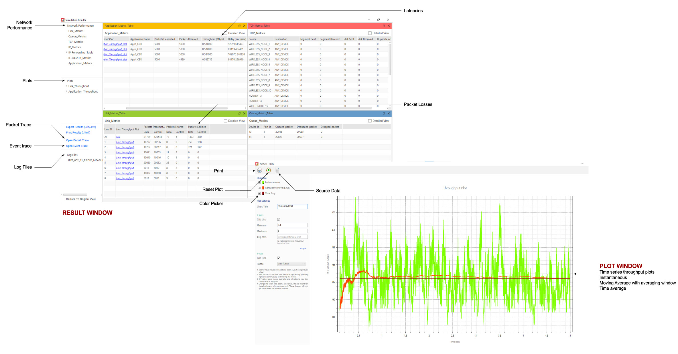
The NetSim results dashboard and plots window shown after a 5G NR run.
The 5G NR protocol stack
Specifications modelled from the 5G Core down to the radio, aligned to the relevant 3GPP series. Every band, numerology, and timer below is configurable.
5G Core
- Functions and interfaces based on TS 23.501 and TS 23.502
- Interfaces: N1/N2, N3, N4, N6, N11, XN
- Core devices: SMF, AMF, UPF
SA and NSA modes
- 5G SA (standalone) architecture
- 5G NSA for LTE–5G dual connectivity, leveraging existing LTE RAN/EPC
- NSA options 4, 4a, 7, and 7a
Radio Link Control (38.322)
- TM (transparent), UM (unacknowledged), AM (acknowledged) modes
- Segmentation and reassembly of RLC SDUs
- t-reassembly and t-pollRetransmit timers
Packet Data Convergence (38.323)
- Maintenance of PDCP sequence numbers
- Discard timer and t-Reordering timer
- Transmit and receive buffer maintenance
Medium Access Control
- Multiplexing and de-multiplexing of MAC SDUs onto transport blocks
- Schedulers: Round Robin, Proportional Fair, Max C/I, and PFS with rate guarantee (how the scheduler works)
- Link adaptation:
- Inner loop (ILLA): sets MCS from CQI
- Outer loop (OLLA): adjusts MCS from HARQ ACK/NACK to meet target BLER
- Handover: inter- and intra-frequency, A3-event based, with configurable interruption time, margin, time to trigger, and cell individual offset (CIO)
Network slicing
- Slice types: BE, eMBB, URLLC, MIoT, V2X
- Static resource sharing by percentage of resources allocated
- Dynamic resource sharing via an online machine-learning algorithm
Frame structure & numerology
- Uplink and downlink physical channels, frame structure, and physical resources
- Flexible sub-carrier spacing using multiple numerologies:
- FR1: µ = 0, 1, 2
- FR2: µ = 2, 3
- Carrier aggregation: intra-band and inter-band
- PHY modulations: BPSK, QPSK, 16QAM, 64QAM, 256QAM
Frequency bands
- FR1 TDD: n34, n38, n39, n40, n41, n50, n51, n77, n78, n79
- FR1 FDD: n1, n2, n3, n5, n7, n8, n12, n20, n25, n28, n66, n70, n71, n74
- FR2 TDD: n257, n258, n259, n260, n261, n262, n263
MIMO & beamforming
- gNB antennas: 1, 2, 4, 8, 16, 32, 64, 128; UE antennas: 1, 2, 4, 8, 16
- Spatial channel model (SCM): channel matrix H per Tx/Rx antenna pair
- Gaussian channel with Rayleigh fast fading, i.i.d. Complex Normal (0, 1) per coherence time
- Digital beamforming gain from the eigenvalues of the Gram (Wishart) matrix
- 2D parabolic sector antenna modelling (3GPP TR 37.840)
HARQ, BLER & coding
- HARQ with soft combining
- User-set target BLER, looked up from SINR–BLER data tables
- SINR–BLER data for all MCS (1–28), base graphs (1, 2), and tables (1, 2, 3), generated by an in-house link-level simulator and validated against literature
- Code block segmentation into code blocks (CB) and code block groups (CBG)
Interference & measurements
- Downlink interference: exact geometric, interference over thermal
- Uplink interference: interference over thermal
- Per-TTI radio measurements: SINR, SNR, Rx signal level, pathloss, shadow-fading loss, beamforming gain, CQI, MCS
- Per-gNB pathloss files importable from third-party tools such as MATLAB
RF propagation (38.900)
- Log-distance mean pathloss, log-normal shadowing, Rayleigh fading
- Environments: Rural Macrocell, Urban Macrocell, Urban Microcell, Indoor Office (mixed and open)
- UE position indoor or outdoor; LOS and NLOS states
- Outdoor-to-indoor: high-loss and low-loss models

Radio measurements and resource allocation are logged to data files every TTI.
Featured examples
Worked scenarios from the 5G NR library, ready to load, run, and extend. Each opens the documented study in HTML.
Impact of MAC scheduling algorithms on throughput (multi-UE)
- Round Robin
- Proportional Fair
- Max Throughput
- 3.5 GHz n78 band: 100 MHz and 50 MHz, 4:1 DL-UL ratio
- 26 GHz n258 band: 400 MHz and 200 MHz, 4:1 DL-UL ratio
gNB cell radius for different link budgets
- 3.5 GHz n78 band (C band)
- 26 GHz n258 band (mmWave band)
5G NR white papers
Worked studies that build a scenario in NetSim and validate the results against 3GPP analysis.

5G NR physical layer
- The time-frequency resource grid in the OFDM access scheme
- How a packet is transmitted over the OFDM PHY in NetSim
- Analytical vs. simulated application throughput

MIMO beamforming: MISO & SIMO
- MIMO, MISO, and SIMO
- The Rayleigh fading channel
- Beamforming gain vs. antenna count, and its effect on throughput

3GPP pathloss models
- Pathloss vs. UE–gNB distance
- Impact of LOS and NLOS states
- Pathloss vs. gNB height and the optimal height

5G handover
- SA–SA, NSA–NSA, NSA–SA
- Handover margin and interruption time
- Buffer fill, transfer, and throughput/latency analysis
Publications that have used NetSim
A sample of peer-reviewed 5G research built and validated in NetSim. See the full list of research papers using NetSim.
Useful links
Documentation, white papers, and support to take a 5G project further.